
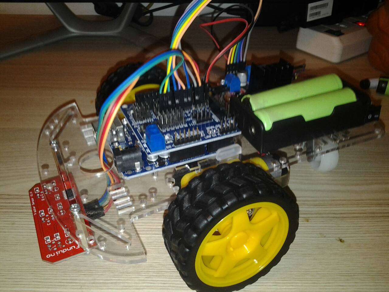
โปรเจค หุ่นยนต์เดินตามเส้น 2WD 3 เซ็นเซอร์ CTRT5000
6 ปีที่ผ่านมา
.
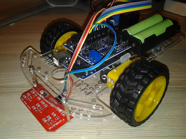

หุ่นยนต์เดินตามเส้น 2WD 3 เซ็นเซอร์ CTRT5000 อุปกรณ์ที่ต้องใช้ก็คือ
1. 2WD Smart Robot Car Chassis Kits
2. Arduino UNO R3 - Made in italy
3. Arduino Sensor Shield V5.0
4. Motor Drive Module L298N
5. สาย Jumper Female to Male ยาว 20cm.
6. สาย Jumper Female to Female ยาว 20cm.
7. รางถ่านแบบ 18650 ใส่ถ่าน 2 ก้อน
8. แบตเตอรี่ลิเธียม 18650 จำนวน 2 ก้อน
9. เสารองแผ่นพีซีบีแบบโลหะ ยาว 25 มม.
10. สกรูหัวกลมน็อตตัวเมีย ขนาด 3มม ยาว10มม.
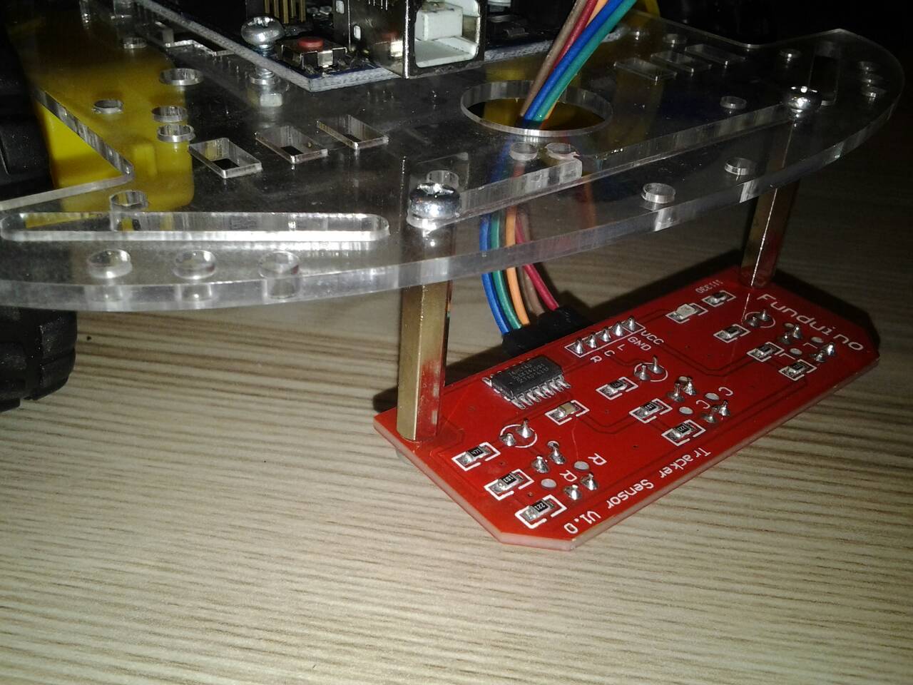
11. 3 Channel CTRT5000 Track Sensor Infrared Line Module
เริ่มต้นด้วยการ ประกอบ 2WD Smart Car Robot Chassis Kits และประกอบ รางถ่านแบบ 18650 และ เชื่อมต่อ Motor Drive Module L298N เข้ากับ Arduino Sensor Shield V 5.0 วงจรตามรูป
หมายเหตุ : ถ้ามี Jumper อยู่ที่ขา ENA และ ENB ของ บอร์ด L298N ให้ถอดออก


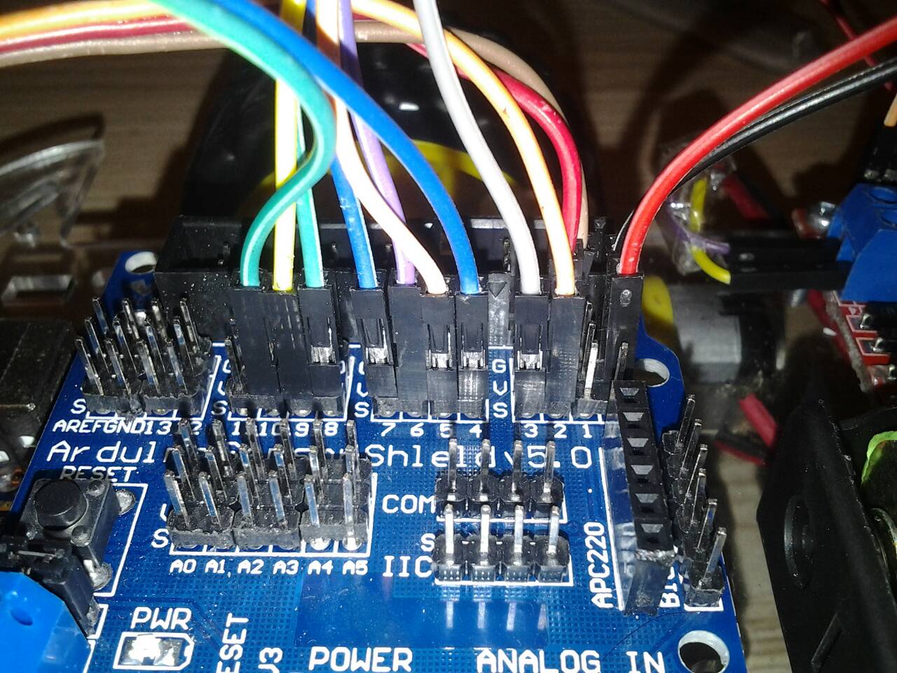
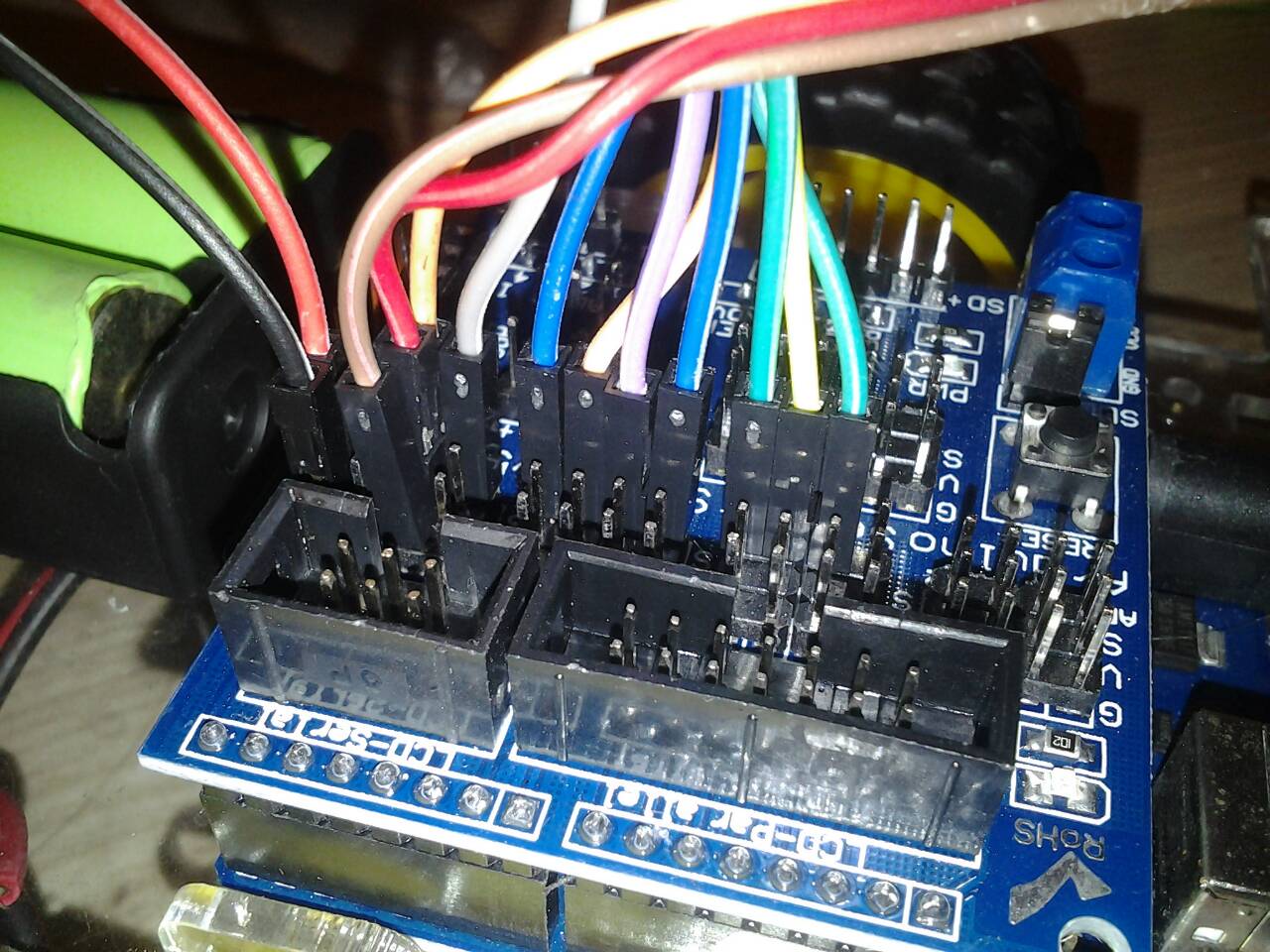
การเชื่อมต่อระหว่าง บอร์ด Arduino Sensor Shield V5.0 กับ บอร์ด L298N

*** VCC ของ Arduino Sensor Shield V5.0 คือ V ***
ประกอบ 2WD Smart Car Robot Chassis Kits และประกอบ รางถ่านแบบ 18650 และ เชื่อมต่อ 5V และ GND ของ Motor Drive Module L298N เข้ากับ V และ G ของ Arduino Sensor Shield

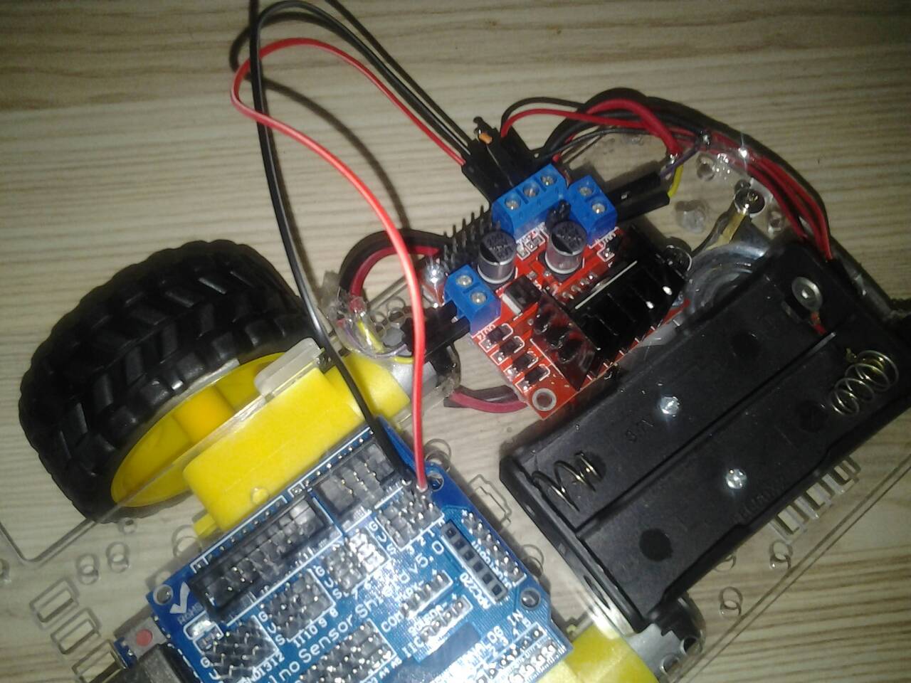
เชื่อมต่อการควบคุมมอเตอร์ ของ Motor Drive Module L298N เข้ากับ Arduino Sensor Shield


หลังจากนั้นให้ทดสอบเบื้องต้น ว่าการหมุนของล้อถูกต้องหรือไม่ โดย
เปิดโปรแกรม Arduino (IDE) และ Upload โค้ดนี้ ไปยัง บอร์ด Arduino UNO R3
// Motor A pins (enableA = enable motor, pinA1 = forward, pinA2 = backward)
int enableA = 3;
int pinA1 = 6;
int pinA2 = 7;
//Motor B pins (enabledB = enable motor, pinB2 = forward, pinB2 = backward)
int enableB = 5;
int pinB1 = 8;
int pinB2 = 9;
//This lets you run the loop a single time for testing
boolean run = true;
void setup() {
pinMode(enableA, OUTPUT);
pinMode(pinA1, OUTPUT);
pinMode(pinA2, OUTPUT);
pinMode(enableB, OUTPUT);
pinMode(pinB1, OUTPUT);
pinMode(pinB2, OUTPUT);
}
void loop() {
if (run) {
delay(2000);
enableMotors();
//Go forward
forward(200);
//Go backward
backward(200);
//Turn left
turnLeft(400);
coast(200);
//Turn right
turnRight(400);
coast(200);
//This stops the loop
run = false;
}
}
//Define high-level H-bridge commands
void enableMotors()
{
motorAOn();
motorBOn();
}
void disableMotors()
{
motorAOff();
motorBOff();
}
void forward(int time)
{
motorAForward();
motorBForward();
delay(time);
}
void backward(int time)
{
motorABackward();
motorBBackward();
delay(time);
}
void turnLeft(int time)
{
motorABackward();
motorBForward();
delay(time);
}
void turnRight(int time)
{
motorAForward();
motorBBackward();
delay(time);
}
void coast(int time)
{
motorACoast();
motorBCoast();
delay(time);
}
void brake(int time)
{
motorABrake();
motorBBrake();
delay(time);
}
//Define low-level H-bridge commands
//enable motors
void motorAOn()
{
digitalWrite(enableA, HIGH);
}
void motorBOn()
{
digitalWrite(enableB, HIGH);
}
//disable motors
void motorAOff()
{
digitalWrite(enableB, LOW);
}
void motorBOff()
{
digitalWrite(enableA, LOW);
}
//motor A controls
void motorAForward()
{
digitalWrite(pinA1, HIGH);
digitalWrite(pinA2, LOW);
}
void motorABackward()
{
digitalWrite(pinA1, LOW);
digitalWrite(pinA2, HIGH);
}
//motor B controls
void motorBForward()
{
digitalWrite(pinB1, HIGH);
digitalWrite(pinB2, LOW);
}
void motorBBackward()
{
digitalWrite(pinB1, LOW);
digitalWrite(pinB2, HIGH);
}
//coasting and braking
void motorACoast()
{
digitalWrite(pinA1, LOW);
digitalWrite(pinA2, LOW);
}
void motorABrake()
{
digitalWrite(pinA1, HIGH);
digitalWrite(pinA2, HIGH);
}
void motorBCoast()
{
digitalWrite(pinB1, LOW);
digitalWrite(pinB2, LOW);
}
void motorBBrake()
{
digitalWrite(pinB1, HIGH);
digitalWrite(pinB2, HIGH);
}
ใส่ แบตเตอรี่ลิเธียม 18650 จำนวน 2 ก้อน ไปที่ รางถ่าน และ ตรวจสอบขั้วของแบตเตอรี่ ใส่ถุกต้องหรือไม่
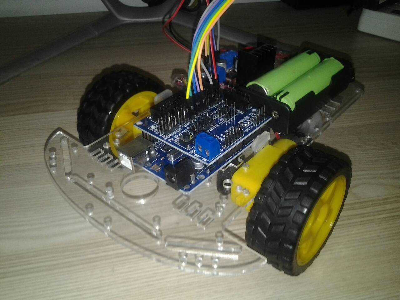
โปรแกรมนี้จะทำงานเพียง 1 ครั้ง ถ้าต้องการทดลองใหม่ให้ถอด แบตเตอรี่ออก (หรือ ปิดเปิด สวิทช์ไฟใหม่) แล้วใส่เข้าไปใหม่ เมื่อล้อหมุน ตรวจสอบการหมุน ขอล้อต่างๆถูกต้องหรือไม่ ถ้าต่อวงจรถูกต้อง ล้อ ทั้งสองข้างจะหมุนไปข้างหน้า 1ครั้ง กลับหลัง 1 ครั้ง และ เดินหน้าอีกหนึ่งครั้งแล้วจึงหยุด ถ้าไม่ถูกต้องให้แก้ไข เช่นการต่อขั้วของมอเตอร์ผิด เป็นต้น
ถ้าทุกอย่างถูกต้อง ทดลอง ยกลงวางที่พื้นแล้วทดสอบ อีกครั้ง ถอด แบตเตอรี่ออก (หรือ ปิดเปิด สวิทช์ไฟใหม่) แล้วใส่เข้าไปใหม่ ถ้าทุกอย่างถูกต้อง รถจะเคลื่อนที่ไปข้างหน้า-ถอยหลัง แล้ว เลี้ยวซ้าย แล้ว จึงกลับสู่ตำแหน่งเดิม
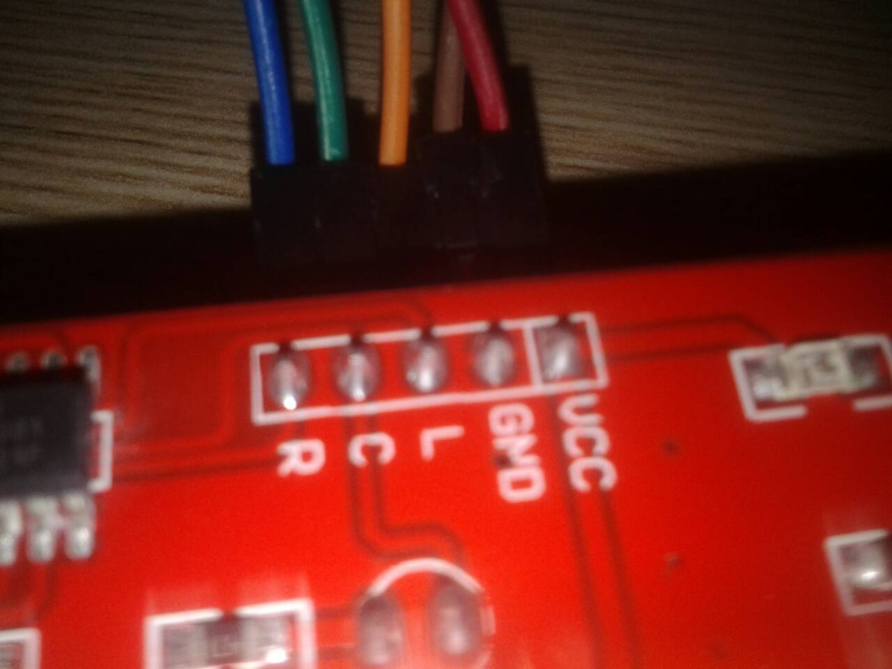
จากนั้นประกอบ 3 Channel CTRT5000 เข้ากับ บอร์ด Arduino Sensor Shield V5.0

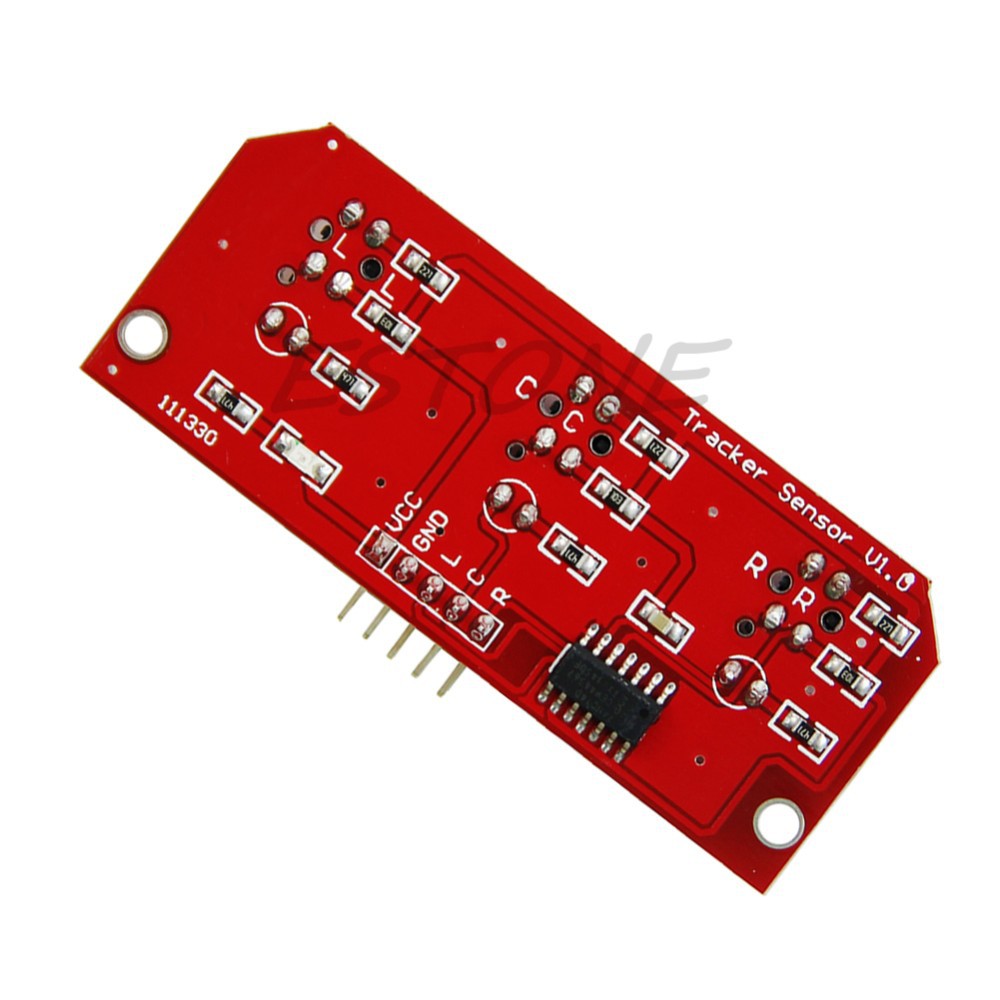
การเชื่อมต่อระหว่าง บอร์ด Sensor Shield กับ บอร์ดเซ็นเซอร์ CTRT5000
Arduino Shield -> CTRT5000
V -> VCC
G -> GND
D2 -> L
D10 -> C
D4 -> R

เพื่อให้ เซ็นเซอร์ อยู่ใกล้พื้น และ ตรวจจับเส้นได้ดียิ่งชึ้น จึงใช้ เสารองแผ่นพีซีบีแบบโลหะ ยาว 25 มม.ใสระหว่างตัวรถกับ 3 Channel CTRT5000
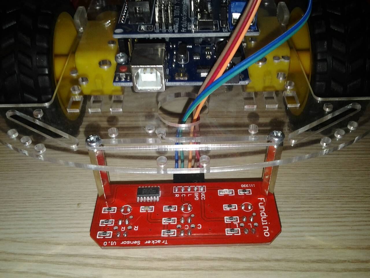
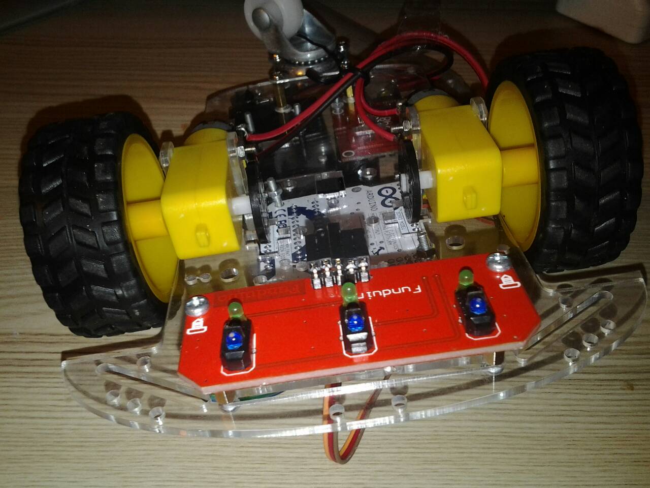
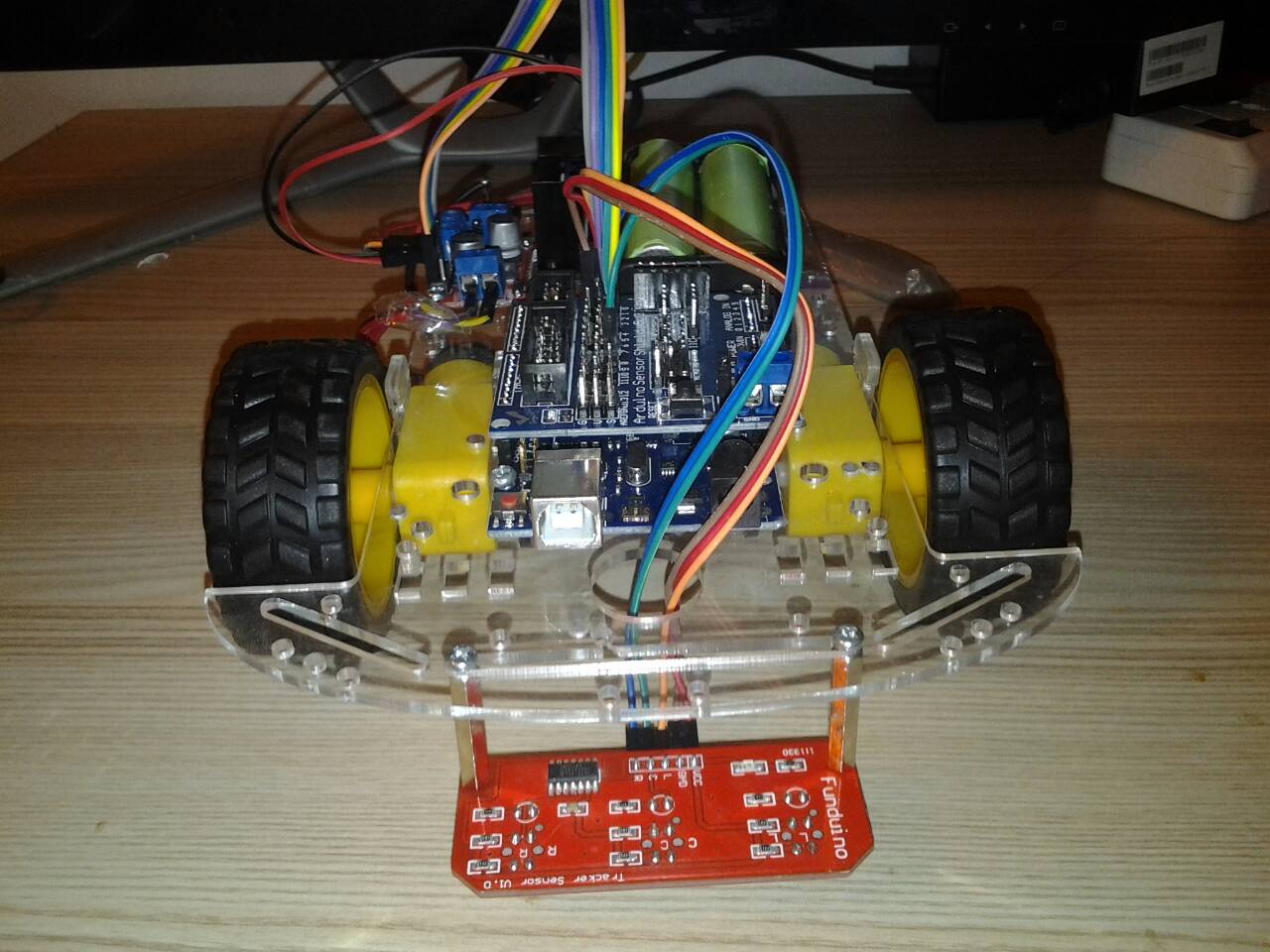
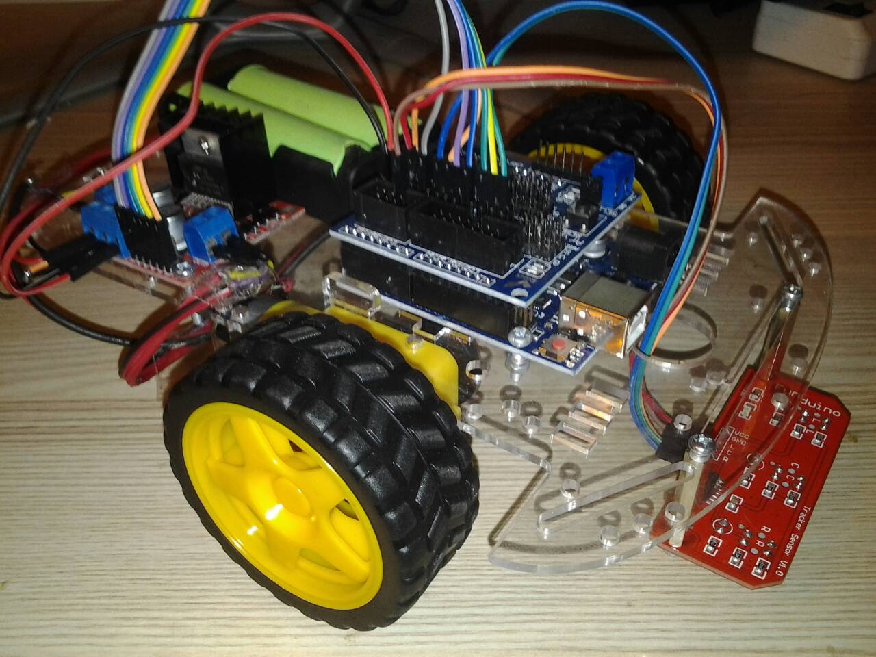
ภาพรวมการต่อ โปรเจค 2WD หุ่นยนต์เดินตามเส้น 3 เซ็นเซอร์ CTRT5000
หลักการทำงานของ เซ็นเซอร์ CTRT5000 ก็คือถ้าพบพื้นสีขาว ค่าที่อ่านได้ = 1 (NOLINE) และ เมื่อพบเทปสีดำ ค่าที่อ่านได้ = 0 (LINE)
เราจึงะนำค่าที่แตกต่างกันของเซ็นเซอร์ ทั้ง 3 ตัว มาใช้เป็นเงื่อนไขตัวอย่างในการเขียนโปรแกรม ดังนี้
L - C - R
1 - 0 - 1 ให้หุ่นยนต์เดินหน้า
0 - 1 - 1 ให้หุ่นยนต์เลี้ยวซ้าย
1 - 1 - 0 ให้หุ่นยนต์เลี้ยวขวา
0 - 0 - 0 ให้หุ่นยนต์หยุด
1 - 1 - 1 ให้หุ่นยนต์ถอยหลัง
0 - 0 - 1 ให้หุ่นยนต์เลี้ยวซ้าย 90 องศา
1 - 0 - 0 ให้หุ่นยนต์เลี้ยวขวา 90 องศา
จากนั้นทดสอบ หุ่นยนต์เดินตามเส้น 2 WD 3 เซ็นเซอร์ CTRT5000 ได้โดย Upload โค้ดนี้ ไปยัง บอร์ด Arduino UNO R3
// connect the sensors to digital pins
#define LEFT_SENSORPIN 2
#define CENTER_SENSORPIN 10
#define RIGHT_SENSORPIN 4
// do you have black line on white ground or white line on black ground?
#define LINE LOW
#define NOLINE HIGH
// define some symbolic constants for our driving directions
enum {GO_AHEAD, GO_LEFT, GO_RIGHT, STOP, GO_POWERLEFT, GO_POWERRIGHT, GO_BACK};
// Motor A pins (enableA = enable motor, pinA1 = forward, pinA2 = backward)
int enableA = 3;
int pinA1 = 6;
int pinA2 = 7;
//Motor B pins (enabledB = enable motor, pinB2 = forward, pinB2 = backward)
int enableB = 5;
int pinB1 = 8;
int pinB2 = 9;
void setup()
{
Serial.begin(9600);
Serial.println("*** LINE FOLLOWER ***");
pinMode(LEFT_SENSORPIN, INPUT);
pinMode(CENTER_SENSORPIN, INPUT);
pinMode(RIGHT_SENSORPIN, INPUT);
pinMode(enableA, OUTPUT);
pinMode(pinA1, OUTPUT);
pinMode(pinA2, OUTPUT);
pinMode(enableB, OUTPUT);
pinMode(pinB1, OUTPUT);
pinMode(pinB2, OUTPUT);
}
void loop()
{
//Run the motors at slightly less than full power
enableMotors();
analogWrite(enableA, 120); // ปรับความเร็วหุ่นยนต์
analogWrite(enableB, 120); // ปรับความเร็วหุ่นยนต์
// read input from sensors
byte leftSensor = digitalRead(LEFT_SENSORPIN);
byte centerSensor = digitalRead(CENTER_SENSORPIN);
byte rightSensor = digitalRead(RIGHT_SENSORPIN);
// calculate direction
byte goDirection;
// if only center sensor detects line, go straight ahead
if (leftSensor == NOLINE && centerSensor == LINE && rightSensor == NOLINE)
goDirection = GO_AHEAD;
// if only left sensor detects line, turn left
else if (leftSensor == LINE && centerSensor == NOLINE && rightSensor == NOLINE)
goDirection = GO_LEFT;
// if only right sensor detects line, turn right
else if (leftSensor == NOLINE && centerSensor == NOLINE && rightSensor == LINE)
goDirection = GO_RIGHT;
// if no sensor detects any line: we are either finished or out of control and will stop
else if (leftSensor == LINE && centerSensor == LINE && rightSensor == LINE)
goDirection = STOP;
else if (leftSensor == NOLINE && centerSensor == NOLINE && rightSensor == NOLINE)
goDirection = GO_BACK;
// if left and center sensor detect line, must be 90° turn to the left
else if (leftSensor == LINE && centerSensor == LINE && rightSensor == NOLINE)
goDirection = GO_POWERLEFT;
// if right and center sensor detect line, must be 90° turn to the right
else if (leftSensor == NOLINE && centerSensor == LINE && rightSensor == LINE)
goDirection = GO_POWERRIGHT;
// Now we have found the direction,
// show it on Serial and control motors accordingly
switch (goDirection)
{
case GO_AHEAD:
Serial.println("Go ahead");
forward(1);
break;
case GO_RIGHT:
Serial.println("Turn right");
turnRight(100);
forward(1);
break;
case GO_LEFT:
Serial.println("Turn left");
turnLeft(100);
forward(1);
break;
case STOP:
Serial.println("No line detected - STOP!");
coast(300);
disableMotors();
break;
case GO_BACK:
Serial.println("No line detected - BACK!");
backward(1);
break;
case GO_POWERLEFT:
Serial.println("Power-turn 90 degrees left");
coast(10);
turnLeft(300);
break;
case GO_POWERRIGHT:
Serial.println("Power-turn 90 degrees right");
coast(10);
turnRight(300);
break;
}
}
//Define high-level H-bridge commands
void enableMotors()
{
motorAOn();
motorBOn();
}
void disableMotors()
{
motorAOff();
motorBOff();
}
void forward(int time)
{
motorAForward();
motorBForward();
delay(time);
}
void backward(int time)
{
motorABackward();
motorBBackward();
delay(time);
}
void turnLeft(int time)
{
motorABackward();
motorBForward();
delay(time);
}
void turnRight(int time)
{
motorAForward();
motorBBackward();
delay(time);
}
void coast(int time)
{
motorACoast();
motorBCoast();
delay(time);
}
void brake(int time)
{
motorABrake();
motorBBrake();
delay(time);
}
//Define low-level H-bridge commands
//enable motors
void motorAOn()
{
digitalWrite(enableA, HIGH);
}
void motorBOn()
{
digitalWrite(enableB, HIGH);
}
//disable motors
void motorAOff()
{
digitalWrite(enableB, LOW);
}
void motorBOff()
{
digitalWrite(enableA, LOW);
}
//motor A controls
void motorAForward()
{
digitalWrite(pinA1, HIGH);
digitalWrite(pinA2, LOW);
}
void motorABackward()
{
digitalWrite(pinA1, LOW);
digitalWrite(pinA2, HIGH);
}
//motor B controls
void motorBForward()
{
digitalWrite(pinB1, HIGH);
digitalWrite(pinB2, LOW);
}
void motorBBackward()
{
digitalWrite(pinB1, LOW);
digitalWrite(pinB2, HIGH);
}
//coasting and braking
void motorACoast()
{
digitalWrite(pinA1, LOW);
digitalWrite(pinA2, LOW);
}
void motorABrake()
{
digitalWrite(pinA1, HIGH);
digitalWrite(pinA2, HIGH);
}
void motorBCoast()
{
digitalWrite(pinB1, LOW);
digitalWrite(pinB2, LOW);
}
void motorBBrake()
{
digitalWrite(pinB1, HIGH);
digitalWrite(pinB2, HIGH);
}
วีดีโอผลลัพธ์การทำงานของ โปรเจค หุ่นยนต์เดินตามเส้น 2WD 3 เซ็นเซอร์ CTRT5000
.

BLOG

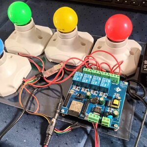
โปรเจค Arduino 3 in 1 หรี่ไฟบ้าน 220V ด้วยแอปมือถือ / ด้วยขวดโค๊ก / ด้วยท่าทางมือ
1 ปีที่ผ่านมา
ชุดคิท Arduino 3 in 1 หรี่ไฟบ้าน 220V ด้วย แอปมือถือ / ขวดโค๊ก / ท่าทางมือ (Gestures) การเรียนรู้การสร้างระบบหรี่ไฟบ้าน 220V โดยใช้ Arduino มีข้อดีหลายประการ ดังนี้: พัฒนาทักษะด้านอิเล็กทรอนิกส์: การสร้างระบบนี้ช่วยให้คุณได้ฝึกทักษะการทำงานกับวงจรไฟฟ…
1 ปีที่ผ่านมา
ชุดคิท Arduino 3 in 1 หรี่ไฟบ้าน 220V ด้วย แอปมือถือ / ขวดโค๊ก / ท่าทางมือ (Gestures) การเรียนรู้การสร้างระบบหรี่ไฟบ้าน 220V โดยใช้ Arduino มีข้อดีหลายประการ ดังนี้: พัฒนาทักษะด้านอิเล็กทรอนิกส์: การสร้างระบบนี้ช่วยให้คุณได้ฝึกทักษะการทำงานกับวงจรไฟฟ…
โปรเจค ESP32 เปิด-ปิดไฟบ้าน 220V ผ่านอินเตอร์เน็ต ได้ทั่วโลก ด้วย Blynk 2.0
1 ปีที่ผ่านมา
ชุดคิท IoT ESP32 2 in 1 เปิดปิดไฟ ผ่าน อินเตอร์เน็ต ด้วย BLYNK / ESP Rainmaker Blynk คือ แพลตฟอร์ม IoT ที่ช่วยให้ผู้ใช้สามารถควบคุมและติดตามอุปกรณ์ผ่านอินเทอร์เน็ตได้ง่าย ๆ โดยไม่ต้องเขียนโค้ดซับซ้อน มีแอปพลิเคชันบนสมาร์ทโฟนที่สามารถออกแบบ UI เพื่อคว…
1 ปีที่ผ่านมา
ชุดคิท IoT ESP32 2 in 1 เปิดปิดไฟ ผ่าน อินเตอร์เน็ต ด้วย BLYNK / ESP Rainmaker Blynk คือ แพลตฟอร์ม IoT ที่ช่วยให้ผู้ใช้สามารถควบคุมและติดตามอุปกรณ์ผ่านอินเทอร์เน็ตได้ง่าย ๆ โดยไม่ต้องเขียนโค้ดซับซ้อน มีแอปพลิเคชันบนสมาร์ทโฟนที่สามารถออกแบบ UI เพื่อคว…
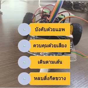
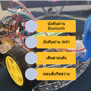
โปรเจค หุ่นยนต์ Arduino 4in1 - บังคับด้วยแอพ / ควบคุมด้วยเสียงปรบมือ / เดินตามเส้น / หลบสิ่งกีดขวาง
1 ปีที่ผ่านมา
ชุดคิท หุ่นยนต์ Arduino 4in1 - บังคับด้วยแอพ / ควบคุมด้วยเสียงปรบมือ / เดินตามเส้น / หลบสิ่งกีดขวาง แบบ DIY (มี ขั้นตอนวิธีทำ และ โค้ด)ชุดคิท หุ่นยนต์ Arduino 4in1 ชุดนี้ สามารถ ทดสอบ ทำโปรเจค ได้หลากหลายรูปแบบ เหมาะสำหรับ โรงเรียน สถานศึกษา ใช้ในการ…
1 ปีที่ผ่านมา
ชุดคิท หุ่นยนต์ Arduino 4in1 - บังคับด้วยแอพ / ควบคุมด้วยเสียงปรบมือ / เดินตามเส้น / หลบสิ่งกีดขวาง แบบ DIY (มี ขั้นตอนวิธีทำ และ โค้ด)ชุดคิท หุ่นยนต์ Arduino 4in1 ชุดนี้ สามารถ ทดสอบ ทำโปรเจค ได้หลากหลายรูปแบบ เหมาะสำหรับ โรงเรียน สถานศึกษา ใช้ในการ…
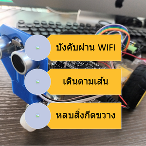
โปรเจค หุ่นยนต์ ESP8266 3in1 - บังคับผ่าน WIFI / เดินตามเส้น / หลบสิ่งกีดขวาง
1 ปีที่ผ่านมา
ชุดคิท หุ่นยนต์ ESP8266 3in1 - บังคับผ่าน WIFI / เดินตามเส้น / หลบสิ่งกีดขวาง แบบ DIY (มี ขั้นตอนวิธีทำ และ โค้ด)ชุดคิท หุ่นยนต์ ESP8266 V3 3in1 ชุดนี้ สามารถ ทดสอบ ทำโปรเจค ได้หลากหลายรูปแบบ เหมาะสำหรับ โรงเรียน สถานศึกษา ใช้ในการเรียนรู้การสร้างหุ่…
1 ปีที่ผ่านมา
ชุดคิท หุ่นยนต์ ESP8266 3in1 - บังคับผ่าน WIFI / เดินตามเส้น / หลบสิ่งกีดขวาง แบบ DIY (มี ขั้นตอนวิธีทำ และ โค้ด)ชุดคิท หุ่นยนต์ ESP8266 V3 3in1 ชุดนี้ สามารถ ทดสอบ ทำโปรเจค ได้หลากหลายรูปแบบ เหมาะสำหรับ โรงเรียน สถานศึกษา ใช้ในการเรียนรู้การสร้างหุ่…
โปรเจค หุ่นยนต์ ESP32 5 in 1 - บังคับผ่าน Bluetooth / บังคับผ่าน WIFI / บังคับผ่านอินเตอร์เน็ต / เดินตามเส้น / หลบสิ่งกีดขวาง
1 ปีที่ผ่านมา
ชุดคิท หุ่นยนต์ ESP32 5 in 1 - บังคับผ่าน Bluetooth / บังคับผ่าน WIFI / บังคับ ผ่านอินเตอร์เน็ต/ เดินตามเส้น / หลบสิ่งกีดขวาง แบบ DIY (มี ขั้นตอนวิธีทำ และ โค้ด)ชุดคิท หุ่นยนต์ ESP32 4in1 ชุดนี้ สามารถ ทดสอบ ทำโปรเจค ได้หลากหลายรูปแบบ เหมาะสำหรับ โรง…
1 ปีที่ผ่านมา
ชุดคิท หุ่นยนต์ ESP32 5 in 1 - บังคับผ่าน Bluetooth / บังคับผ่าน WIFI / บังคับ ผ่านอินเตอร์เน็ต/ เดินตามเส้น / หลบสิ่งกีดขวาง แบบ DIY (มี ขั้นตอนวิธีทำ และ โค้ด)ชุดคิท หุ่นยนต์ ESP32 4in1 ชุดนี้ สามารถ ทดสอบ ทำโปรเจค ได้หลากหลายรูปแบบ เหมาะสำหรับ โรง…
โปรเจค ESP32 เปิด-ปิดไฟ ผ่านอินเตอร์เน็ตด้วย ESP Rainmaker
1 ปีที่ผ่านมา
ESP RainMaker เป็นแพลตฟอร์มที่ช่วยให้นักพัฒนาสร้างอุปกรณ์ที่เชื่อมต่อกับ ESP32-S2 SoC ของ Espressif โดยไม่ต้องวุ่นวายกับการจัดการโครงสร้างพื้นฐาน มี SDK ของอุปกรณ์ แอปโทรศัพท์ที่ปรับเปลี่ยนได้เอง มิดเดิลแวร์คลาวด์แบบโปร่งใส และยูทิลิตีโฮสต์เพื่อลดควา…
1 ปีที่ผ่านมา
ESP RainMaker เป็นแพลตฟอร์มที่ช่วยให้นักพัฒนาสร้างอุปกรณ์ที่เชื่อมต่อกับ ESP32-S2 SoC ของ Espressif โดยไม่ต้องวุ่นวายกับการจัดการโครงสร้างพื้นฐาน มี SDK ของอุปกรณ์ แอปโทรศัพท์ที่ปรับเปลี่ยนได้เอง มิดเดิลแวร์คลาวด์แบบโปร่งใส และยูทิลิตีโฮสต์เพื่อลดควา…

โปรเจค Arduino เปิด-ปิดไฟ ด้วย โทรศัพท์ ผ่าน แอพบลูทูธ
1 ปีที่ผ่านมา
โปรเจค Arduino: เปิด-ปิดไฟด้วย โทรศัพท์ ผ่าน แอพบลูทูธ การควบคุมการเปิด-ปิดไฟในบ้านหรือสถานที่ต่าง ๆ ได้ง่ายขึ้นด้วยการใช้ Arduino ร่วมกับบลูทูธ. ในบทความนี้, เราจะสร้างโปรเจคที่ใช้ Arduino เพื่อควบคุมไฟผ่านแอพบลูทูธบนโทรศัพท์มือถือของเรา. การทำโปรเจ…
1 ปีที่ผ่านมา
โปรเจค Arduino: เปิด-ปิดไฟด้วย โทรศัพท์ ผ่าน แอพบลูทูธ การควบคุมการเปิด-ปิดไฟในบ้านหรือสถานที่ต่าง ๆ ได้ง่ายขึ้นด้วยการใช้ Arduino ร่วมกับบลูทูธ. ในบทความนี้, เราจะสร้างโปรเจคที่ใช้ Arduino เพื่อควบคุมไฟผ่านแอพบลูทูธบนโทรศัพท์มือถือของเรา. การทำโปรเจ…
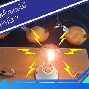
โปรเจค Arduino ไฟฟ้าจากผลไม้ กับ หลอดไฟ 220 โวลต์
1 ปีที่ผ่านมา
สอนทำโปรเจค Arduino ไฟฟ้าจากผลไม้ กับ หลอดไฟ 220 โวลต์ "ทดลองไฟฟ้าจากผลไม้" เป็นการทดลองทางวิทยาศาสตร์ที่น่าสนใจเพื่อศึกษาและทดสอบกระบวนการผลิตไฟฟ้าโดยใช้มันฝรั่งในฐานะวัตถุดิบหลัก. การทดลองนี้มุ่งเน้นการเรียนรู้และทำความเข้าใจถึงพลังงานที่เกิดขึ้นจา…
1 ปีที่ผ่านมา
สอนทำโปรเจค Arduino ไฟฟ้าจากผลไม้ กับ หลอดไฟ 220 โวลต์ "ทดลองไฟฟ้าจากผลไม้" เป็นการทดลองทางวิทยาศาสตร์ที่น่าสนใจเพื่อศึกษาและทดสอบกระบวนการผลิตไฟฟ้าโดยใช้มันฝรั่งในฐานะวัตถุดิบหลัก. การทดลองนี้มุ่งเน้นการเรียนรู้และทำความเข้าใจถึงพลังงานที่เกิดขึ้นจา…
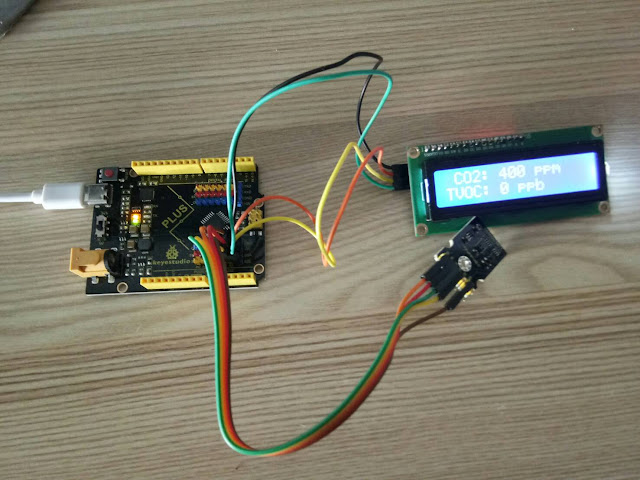
มินิโปรเจค Arduino วัดก๊าซคาร์บอนไดออกไซด์ แสดงผลที่จอ LCD
4 ปีที่ผ่านมา
ระดับคาร์บอนไดออกไซด์ปกติ (Normal CO2 Levels) ระดับคาร์บอนไดออกไซด์ปกติผลกระทบของ CO2 ต่อผู้ใหญ่ที่มีสุขภาพที่ดีสามารถสรุปได้ดังนี้-ระดับกลางแจ้งปกติ: 350 – 450 ppm-ระดับที่ยอมรับได้: <600 ppm=”” span=””>-ข้อร้องเร…
4 ปีที่ผ่านมา
ระดับคาร์บอนไดออกไซด์ปกติ (Normal CO2 Levels) ระดับคาร์บอนไดออกไซด์ปกติผลกระทบของ CO2 ต่อผู้ใหญ่ที่มีสุขภาพที่ดีสามารถสรุปได้ดังนี้-ระดับกลางแจ้งปกติ: 350 – 450 ppm-ระดับที่ยอมรับได้: <600 ppm=”” span=””>-ข้อร้องเร…
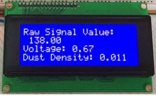
มินิโปรเจค Arduino เครื่องวัดฝุ่น PM2.5 ด้วย เซ็นเซอร์ GP2Y1014AU
4 ปีที่ผ่านมา
เครื่องวัดฝุ่น PM2.5 ด้วย เซ็นเซอร์ GP2Y1014AU บทความนี้ กล่าวถึงขั้นตอนการทำงานโปรเจค เครื่องวัดฝุ่น PM2.5 กับ Arduino UNO โดยใช้ เซ็นเซอร์วัดฝุ่น PM2.5 Keyestudio GP2Y1014AU ของ Sharp เซ็นเซอร์ฝุ่นนี้มีขนาดเล็กและสามารถตรวจจับฝุ่นละอองและอนุภาคควัน…
4 ปีที่ผ่านมา
เครื่องวัดฝุ่น PM2.5 ด้วย เซ็นเซอร์ GP2Y1014AU บทความนี้ กล่าวถึงขั้นตอนการทำงานโปรเจค เครื่องวัดฝุ่น PM2.5 กับ Arduino UNO โดยใช้ เซ็นเซอร์วัดฝุ่น PM2.5 Keyestudio GP2Y1014AU ของ Sharp เซ็นเซอร์ฝุ่นนี้มีขนาดเล็กและสามารถตรวจจับฝุ่นละอองและอนุภาคควัน…
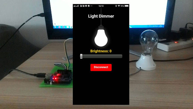
มินิโปรเจค Arduino หรี่ไฟ AC 220V ผ่านบลูทูธ ด้วย App Android
5 ปีที่ผ่านมา
หรี่ไฟ AC 220V ผ่านบลูทูธ ด้วย App Android เป้าหมายและหลักการทำงานของโปรเจค ต้องการหรี่ไฟ หรือควบคุมแสงสว่างของหลอดไฟหรืออุปกรณ์ไฟฟ้าอื่นๆ แบบไร้สายผ่านโทรศัพท์มือถือด้วยแอพแอนดรอยด์ (App Android) เพื่อเป็นการประหยัดพลังงาน และความสะดวกในการควบคุม ซึ…
5 ปีที่ผ่านมา
หรี่ไฟ AC 220V ผ่านบลูทูธ ด้วย App Android เป้าหมายและหลักการทำงานของโปรเจค ต้องการหรี่ไฟ หรือควบคุมแสงสว่างของหลอดไฟหรืออุปกรณ์ไฟฟ้าอื่นๆ แบบไร้สายผ่านโทรศัพท์มือถือด้วยแอพแอนดรอยด์ (App Android) เพื่อเป็นการประหยัดพลังงาน และความสะดวกในการควบคุม ซึ…

มินิโปรเจค สร้างเกม Endless Runner ด้วย Arduino และ จอ LCD
5 ปีที่ผ่านมา
มินิโปรเจค สร้างเกม Endless Runner ด้วย Arduino และ จอ LCD การสร้างเกม ก็คือการเขียนโปรแกรมแบบหนึ่ง ให้แสดงผลถี่ๆ แล้วเขียนโปรแกรมให้การแสดงผลในแต่ละครั้ง ค่อยๆทำให้ตัวละครในภาพค่อยๆขยับ โดยการทำการเปลี่ยนภาพ หรือเคลื่อนที่ตัวละคร ก็จะเกิดการเคลื่อนไ…
5 ปีที่ผ่านมา
มินิโปรเจค สร้างเกม Endless Runner ด้วย Arduino และ จอ LCD การสร้างเกม ก็คือการเขียนโปรแกรมแบบหนึ่ง ให้แสดงผลถี่ๆ แล้วเขียนโปรแกรมให้การแสดงผลในแต่ละครั้ง ค่อยๆทำให้ตัวละครในภาพค่อยๆขยับ โดยการทำการเปลี่ยนภาพ หรือเคลื่อนที่ตัวละคร ก็จะเกิดการเคลื่อนไ…
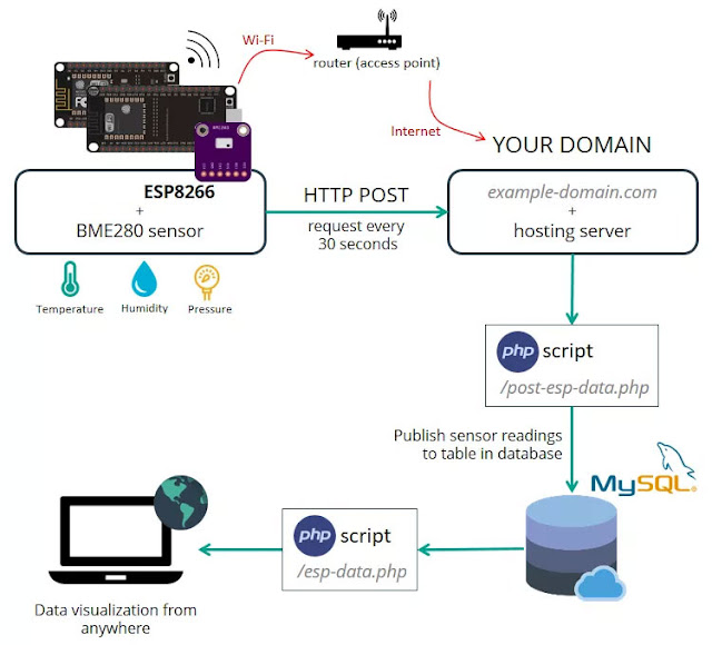
โปรเจค IoT ESP8266 วัดอุณหภูมิ บันทึกลงดาต้าเบส MySQL
5 ปีที่ผ่านมา
เป้าหมายของโปรเจคนี้คือเราต้องดูข้อมูลด้วยการเข้าถึงโดเมน ของเราเอง ไม่ว่าจะอยู่ส่วนไหนของโลก โดย ESP8266 จะสร้างไคลเอ็นต์ ที่ทำให้คำขอ HTTP POST ไปยังสคริปต์ PHP เพื่อแทรกข้อมูล (การอ่านเซ็นเซอร์) ลงในฐานข้อมูล MySQLโดยบทความนี้จะแสดงการส่งข้อมูลจาก…
5 ปีที่ผ่านมา
เป้าหมายของโปรเจคนี้คือเราต้องดูข้อมูลด้วยการเข้าถึงโดเมน ของเราเอง ไม่ว่าจะอยู่ส่วนไหนของโลก โดย ESP8266 จะสร้างไคลเอ็นต์ ที่ทำให้คำขอ HTTP POST ไปยังสคริปต์ PHP เพื่อแทรกข้อมูล (การอ่านเซ็นเซอร์) ลงในฐานข้อมูล MySQLโดยบทความนี้จะแสดงการส่งข้อมูลจาก…
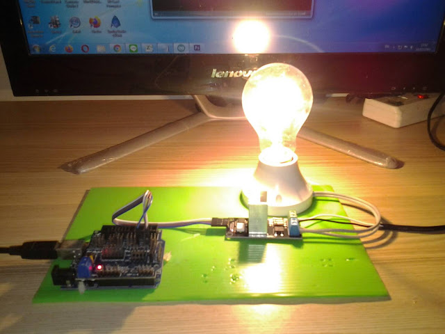
มินิโปรเจค Arduino เปิดปิดไฟ 220V และ หรี่ไฟบ้านด้วยเสียง
5 ปีที่ผ่านมา
ควบคุมการติด-ดับ และ หรี่แสงสว่างหลอดไฟด้วยเสียงปรบมือ แนะนำ : ชุดประกอบสำเร็จ Arduino ควบคุมการติด-ดับ และ หรี่แสงสว่างหลอดไฟด้วยเสียงปรบมือ การทำ มินิโปรเจค Arduino เปิดปิดไฟ 220V และ หรี่ไฟบ้านด้วยเสียง เป้าหมายและหลักการทำงานของโปรเจค ต้องการควบค…
5 ปีที่ผ่านมา
ควบคุมการติด-ดับ และ หรี่แสงสว่างหลอดไฟด้วยเสียงปรบมือ แนะนำ : ชุดประกอบสำเร็จ Arduino ควบคุมการติด-ดับ และ หรี่แสงสว่างหลอดไฟด้วยเสียงปรบมือ การทำ มินิโปรเจค Arduino เปิดปิดไฟ 220V และ หรี่ไฟบ้านด้วยเสียง เป้าหมายและหลักการทำงานของโปรเจค ต้องการควบค…

โปรเจค ESP32-CAM กล้องดักถ่ายภาพอัตโนมัติ ด้วย PIR Motion
5 ปีที่ผ่านมา
โปรเจค ESP32-CAM กล้องดักถ่ายภาพอัตโนมัติ ด้วย PIR Motion โดยโปรเจคนี้ สามารถประยุกต์เป็นกล้องดักถ่ายภาพเมื่อมีผู้บุกรุก หรือเป็นกล้องดักถ่ายภาพสัตว์ มีชื่อเรียกหลายชื่อได้แก่ Trail Cam, Scout Cam, Camera Trap โดยผู้ใช้งานโดยซ่อนไว้ใกล้บริเวณทางที่สั…
5 ปีที่ผ่านมา
โปรเจค ESP32-CAM กล้องดักถ่ายภาพอัตโนมัติ ด้วย PIR Motion โดยโปรเจคนี้ สามารถประยุกต์เป็นกล้องดักถ่ายภาพเมื่อมีผู้บุกรุก หรือเป็นกล้องดักถ่ายภาพสัตว์ มีชื่อเรียกหลายชื่อได้แก่ Trail Cam, Scout Cam, Camera Trap โดยผู้ใช้งานโดยซ่อนไว้ใกล้บริเวณทางที่สั…
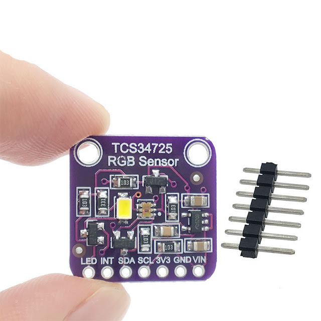
มินิโปรเจค Arduino อ่านค่าสี เล่นไฟล์เสียงจาก SD Card ออกลำโพง
5 ปีที่ผ่านมา
มินิโปรเจค Arduino อ่านค่าสี เล่นไฟล์เสียงจาก SD Card ออกลำโพง โปรเจค Arduino พูดโต้ตอบได้ โดยการเล่นไฟล์เสียงจาก SD Card บทความนี้จะสอนใช้งาน Arduino เล่นไฟล์เสียงจาก SD Card ออกลำโพง เราสามารถอัดเสียงพูดหรือบันทึกเสียงเพลงลง SD Card แล้ว สั่งงานให้…
5 ปีที่ผ่านมา
มินิโปรเจค Arduino อ่านค่าสี เล่นไฟล์เสียงจาก SD Card ออกลำโพง โปรเจค Arduino พูดโต้ตอบได้ โดยการเล่นไฟล์เสียงจาก SD Card บทความนี้จะสอนใช้งาน Arduino เล่นไฟล์เสียงจาก SD Card ออกลำโพง เราสามารถอัดเสียงพูดหรือบันทึกเสียงเพลงลง SD Card แล้ว สั่งงานให้…
 โรบอทสยาม อุปกรณ์หุ่นยนต์ Arduino
สมัครสมาชิกร้านนี้ เพื่อรับสิทธิพิเศษ


▲
▼
รายการสั่งซื้อของฉัน
รายการสั่งซื้อของฉัน
ข้อมูลร้านค้านี้

โรบอทสยาม อุปกรณ์หุ่นยนต์ Arduino
จําหน่าย อุปกรณ์หุ่นยนต์ Arduino , ESP8266, ESP32 , STM32 , micro:bit , Paspberry Pi รับประกอบหุ่นยนต์ ชุดคิทหุ่นยนต์ ตัวอย่างโปรเจค IoT (Internet of Things) อินเทอร์เน็ตของสรรพสิ่ง
เบอร์โทร : 095-226-2116
อีเมล : robotsiam16@gmail.com
อีเมล : robotsiam16@gmail.com
ส่งข้อความติดต่อร้าน
เกี่ยวกับร้านค้านี้
ค้นหาสินค้าในร้านนี้
ค้นหาสินค้า
สินค้าที่ดูล่าสุด
บันทึกเป็นร้านโปรด
Join เป็นสมาชิกร้าน
แชร์หน้านี้
แชร์หน้านี้
↑
TOP เลื่อนขึ้นบนสุด
TOP เลื่อนขึ้นบนสุด
สินค้าในตะกร้า ({{total_num}} รายการ)

ขออภัย ขณะนี้ยังไม่มีสินค้าในตะกร้า
ราคาสินค้าทั้งหมด
฿ {{price_format(total_price)}}
- ฿ {{price_format(discount.price)}}
ราคาสินค้าทั้งหมด
{{total_quantity}} ชิ้น
฿ {{price_format(after_product_price)}}
ราคาไม่รวมค่าจัดส่ง
➜ เลือกซื้อสินค้าเพิ่ม