การใช้งาน ESP32-CAM กล้อง OV2640 เป็น Video Stream ภาพเคลื่อนไหว
6 ปีที่ผ่านมา

การใช้งาน ESP32-CAM กล้อง OV2640 เป็น Video Stream ภาพเคลื่อนไหว แสดงผลขึ้นหน้าเว็บผ่าน WiFi เป็นการทำงานแบบ Station (STA) Mode เป็นโหมดที่กำหนดให้ ESP32 ไปเชื่อมต่อกับอุปกรณ์อื่น ๆ เช่น เร้าเตอร์ แล้วรับส่งข้อมูลระหว่างเครื่องในวงแลนได้ โดยที่ใช้ ESP32 เป็น Server Controller
..
### อุปกรณ์ที่ใช้ ###
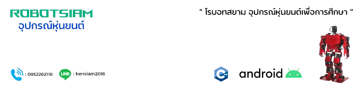
1. ESP32-CAM ESP32 Development Board with Camera Module
2. CP2102 USB 2.0 to UART TTL 5PIN Connector Module
3. Jumper (F2F) 10cm Female to Female
โดยการทำงานมีขั้นตอนดังนี้
1.ติดตั้ง Arduino core for ESP32
ลิงค์การติดตั้ง Arduino core for ESP32
https://robotsiam.blogspot.com/2017/09/arduino-core-for-esp32.html
2.เชื่อมต่ออุปกรณ์
2.1 เชื่อมต่อ ESP32-CAM กับ กล้อง OV2640
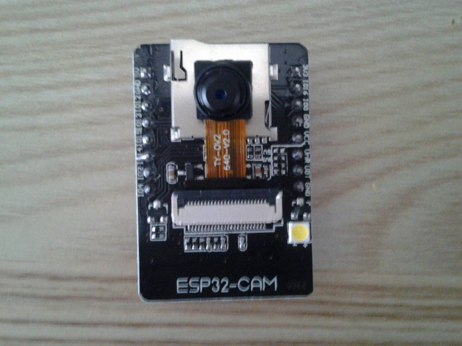
2.2 เชื่อมต่อ ESP32-CAM กับ CP2102 USB to UART TTL


3.อัพโหลดโค้ด
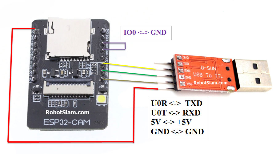
3.1 เชื่อมต่อ CP2102 USB เข้ากับคอมพิวเตอร์
3.2 ตรวจสอบการติดตั้งไดร์เวอร์ ของ CP2102 USB
3.2.1 คลิกขวา Computet -> Properties
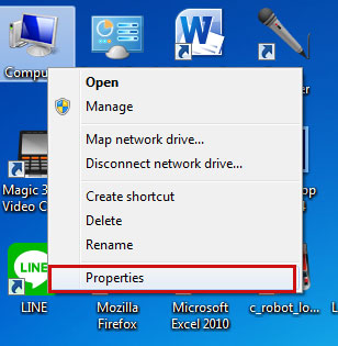
3.2.2 คลิกที่ Device Manager

3.2.3 ที่ Ports (COM & LPT) จะพบ การติดตั้งไดร์เวอร์ ของ CP2102 USB ในตัวอย่างเป็น "COM12"


3.2.4 เปิดโปรแกรม Arduino (IDE) และ ก็อปปี้ โค้ดด้านล่างนี้ ไปวางไว้ในส่วนเขียนโปรแกรม
/*********
Rui Santos
Complete project details at https://RandomNerdTutorials.com

IMPORTANT!!!
- Select Board "ESP32 Wrover Module"
- Select the Partion Scheme "Huge APP (3MB No OTA)
- GPIO 0 must be connected to GND to upload a sketch
- After connecting GPIO 0 to GND, press the ESP32-CAM on-board RESET button to put your board in flashing mode

Permission is hereby granted, free of charge, to any person obtaining a copy
of this software and associated documentation files.

The above copyright notice and this permission notice shall be included in all
copies or substantial portions of the Software.
*********/

#include "esp_camera.h"
#include <WiFi.h>
#include "esp_timer.h"
#include "img_converters.h"
#include "Arduino.h"
#include "fb_gfx.h"
#include "soc/soc.h" //disable brownout problems
#include "soc/rtc_cntl_reg.h" //disable brownout problems
#include "dl_lib.h"
#include "esp_http_server.h"

//Replace with your network credentials
const char* ssid = "REPLACE_WITH_YOUR_SSID";
const char* password = "REPLACE_WITH_YOUR_PASSWORD";

#define PART_BOUNDARY "123456789000000000000987654321"

// This project was tested with the AI Thinker Model, M5STACK PSRAM Model and M5STACK WITHOUT PSRAM
#define CAMERA_MODEL_AI_THINKER
//#define CAMERA_MODEL_M5STACK_PSRAM
//#define CAMERA_MODEL_M5STACK_WITHOUT_PSRAM

// Not tested with this model
//#define CAMERA_MODEL_WROVER_KIT

#if defined(CAMERA_MODEL_WROVER_KIT)
#define PWDN_GPIO_NUM -1
#define RESET_GPIO_NUM -1
#define XCLK_GPIO_NUM 21
#define SIOD_GPIO_NUM 26
#define SIOC_GPIO_NUM 27

#define Y9_GPIO_NUM 35
#define Y8_GPIO_NUM 34
#define Y7_GPIO_NUM 39
#define Y6_GPIO_NUM 36
#define Y5_GPIO_NUM 19
#define Y4_GPIO_NUM 18
#define Y3_GPIO_NUM 5
#define Y2_GPIO_NUM 4
#define VSYNC_GPIO_NUM 25
#define HREF_GPIO_NUM 23
#define PCLK_GPIO_NUM 22

#elif defined(CAMERA_MODEL_M5STACK_PSRAM)
#define PWDN_GPIO_NUM -1
#define RESET_GPIO_NUM 15
#define XCLK_GPIO_NUM 27
#define SIOD_GPIO_NUM 25
#define SIOC_GPIO_NUM 23

#define Y9_GPIO_NUM 19
#define Y8_GPIO_NUM 36
#define Y7_GPIO_NUM 18
#define Y6_GPIO_NUM 39
#define Y5_GPIO_NUM 5
#define Y4_GPIO_NUM 34
#define Y3_GPIO_NUM 35
#define Y2_GPIO_NUM 32
#define VSYNC_GPIO_NUM 22
#define HREF_GPIO_NUM 26
#define PCLK_GPIO_NUM 21

#elif defined(CAMERA_MODEL_M5STACK_WITHOUT_PSRAM)
#define PWDN_GPIO_NUM -1
#define RESET_GPIO_NUM 15
#define XCLK_GPIO_NUM 27
#define SIOD_GPIO_NUM 25
#define SIOC_GPIO_NUM 23

#define Y9_GPIO_NUM 19
#define Y8_GPIO_NUM 36
#define Y7_GPIO_NUM 18
#define Y6_GPIO_NUM 39
#define Y5_GPIO_NUM 5
#define Y4_GPIO_NUM 34
#define Y3_GPIO_NUM 35
#define Y2_GPIO_NUM 17
#define VSYNC_GPIO_NUM 22
#define HREF_GPIO_NUM 26
#define PCLK_GPIO_NUM 21

#elif defined(CAMERA_MODEL_AI_THINKER)
#define PWDN_GPIO_NUM 32
#define RESET_GPIO_NUM -1
#define XCLK_GPIO_NUM 0
#define SIOD_GPIO_NUM 26
#define SIOC_GPIO_NUM 27

#define Y9_GPIO_NUM 35
#define Y8_GPIO_NUM 34
#define Y7_GPIO_NUM 39
#define Y6_GPIO_NUM 36
#define Y5_GPIO_NUM 21
#define Y4_GPIO_NUM 19
#define Y3_GPIO_NUM 18
#define Y2_GPIO_NUM 5
#define VSYNC_GPIO_NUM 25
#define HREF_GPIO_NUM 23
#define PCLK_GPIO_NUM 22
#else
#error "Camera model not selected"
#endif

static const char* _STREAM_CONTENT_TYPE = "multipart/x-mixed-replace;boundary=" PART_BOUNDARY;
static const char* _STREAM_BOUNDARY = "\r\n--" PART_BOUNDARY "\r\n";
static const char* _STREAM_PART = "Content-Type: image/jpeg\r\nContent-Length: %u\r\n\r\n";

httpd_handle_t stream_httpd = NULL;

static esp_err_t stream_handler(httpd_req_t *req){
camera_fb_t * fb = NULL;
esp_err_t res = ESP_OK;
size_t _jpg_buf_len = 0;
uint8_t * _jpg_buf = NULL;
char * part_buf[64];

res = httpd_resp_set_type(req, _STREAM_CONTENT_TYPE);
if(res != ESP_OK){
return res;
}

while(true){
fb = esp_camera_fb_get();
if (!fb) {
Serial.println("Camera capture failed");
res = ESP_FAIL;
} else {
if(fb->width > 400){
if(fb->format != PIXFORMAT_JPEG){
bool jpeg_converted = frame2jpg(fb, 80, &_jpg_buf, &_jpg_buf_len);
esp_camera_fb_return(fb);
fb = NULL;
if(!jpeg_converted){
Serial.println("JPEG compression failed");
res = ESP_FAIL;
}
} else {
_jpg_buf_len = fb->len;
_jpg_buf = fb->buf;
}
}
}
if(res == ESP_OK){
size_t hlen = snprintf((char *)part_buf, 64, _STREAM_PART, _jpg_buf_len);
res = httpd_resp_send_chunk(req, (const char *)part_buf, hlen);
}
if(res == ESP_OK){
res = httpd_resp_send_chunk(req, (const char *)_jpg_buf, _jpg_buf_len);
}
if(res == ESP_OK){
res = httpd_resp_send_chunk(req, _STREAM_BOUNDARY, strlen(_STREAM_BOUNDARY));
}
if(fb){
esp_camera_fb_return(fb);
fb = NULL;
_jpg_buf = NULL;
} else if(_jpg_buf){
free(_jpg_buf);
_jpg_buf = NULL;
}
if(res != ESP_OK){
break;
}
//Serial.printf("MJPG: %uB\n",(uint32_t)(_jpg_buf_len));
}
return res;
}

void startCameraServer(){
httpd_config_t config = HTTPD_DEFAULT_CONFIG();
config.server_port = 80;

httpd_uri_t index_uri = {
.uri = "/",
.method = HTTP_GET,
.handler = stream_handler,
.user_ctx = NULL
};

//Serial.printf("Starting web server on port: '%d'\n", config.server_port);
if (httpd_start(&stream_httpd, &config) == ESP_OK) {
httpd_register_uri_handler(stream_httpd, &index_uri);
}
}

void setup() {
WRITE_PERI_REG(RTC_CNTL_BROWN_OUT_REG, 0); //disable brownout detector

Serial.begin(115200);
Serial.setDebugOutput(false);

camera_config_t config;
config.ledc_channel = LEDC_CHANNEL_0;
config.ledc_timer = LEDC_TIMER_0;
config.pin_d0 = Y2_GPIO_NUM;
config.pin_d1 = Y3_GPIO_NUM;
config.pin_d2 = Y4_GPIO_NUM;
config.pin_d3 = Y5_GPIO_NUM;
config.pin_d4 = Y6_GPIO_NUM;
config.pin_d5 = Y7_GPIO_NUM;
config.pin_d6 = Y8_GPIO_NUM;
config.pin_d7 = Y9_GPIO_NUM;
config.pin_xclk = XCLK_GPIO_NUM;
config.pin_pclk = PCLK_GPIO_NUM;
config.pin_vsync = VSYNC_GPIO_NUM;
config.pin_href = HREF_GPIO_NUM;
config.pin_sscb_sda = SIOD_GPIO_NUM;
config.pin_sscb_scl = SIOC_GPIO_NUM;
config.pin_pwdn = PWDN_GPIO_NUM;
config.pin_reset = RESET_GPIO_NUM;
config.xclk_freq_hz = 20000000;
config.pixel_format = PIXFORMAT_JPEG;

if(psramFound()){
config.frame_size = FRAMESIZE_UXGA;
config.jpeg_quality = 10;
config.fb_count = 2;
} else {
config.frame_size = FRAMESIZE_SVGA;
config.jpeg_quality = 12;
config.fb_count = 1;
}

// Camera init
esp_err_t err = esp_camera_init(&config);
if (err != ESP_OK) {
Serial.printf("Camera init failed with error 0x%x", err);
return;
}
// Wi-Fi connection
WiFi.begin(ssid, password);
while (WiFi.status() != WL_CONNECTED) {
delay(500);
Serial.print(".");
}
Serial.println("");
Serial.println("WiFi connected");

Serial.print("Camera Stream Ready! Go to: http://");
Serial.print(WiFi.localIP());

// Start streaming web server
startCameraServer();
}

void loop() {
delay(1);
}
3.2.5 แก้ไขโค้ด
ก่อนการอัพโหลดต้องแก้ไขโค้ด ตามเครือข่าย WiFi ที่เลือกใช้งาน โดย
"REPLACE_WITH_YOUR_SSID" คือ ชื่อWiFiที่ต้องการเชื่อมต่อ
"REPLACE_WITH_YOUR_PASSWORD" คือ รหัสผ่าน
ตรวจความถูกต้องแบบละเอียด เช่น...ตัวพิมพ์เล็ก , ตัวพิมพ์ใหญ่ อักขระต่างๆ ให้ถูกต้อง


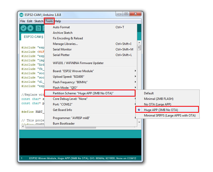
3.2.7 ไปที่ Tools -> Partition Scheme แล้วเลือก Huge APP(3MB No OTA)
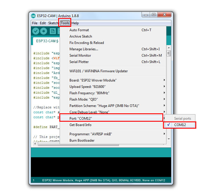
ในตัวอย่างเลือกเป็น "COM12"
 เพื่ออัพโหลด
ตั้งชื่อไฟล์ -> Save โปรแกรม จะทำการ อัพโหลด

3.2.10 หากสามารถอัพโหลดโปรแกรมลงบอร์ดได้สำเร็จ จะแสดงคำว่า Done uploading. ที่แถบด้านล่าง

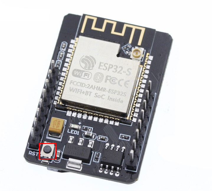
### ถ้ามีปัญหาในการอัพโหลดไม่ได้ ให้กดปุ่ม RST ค้างไว้ในขณะอัพโหลด ###
4.1 เปิดหน้าต่าง Serial Monitor โดยไปที่ Tools > Serial Monitor


4.3 ถอด Jumper ที่เชื่อมต่อระหว่าง IO0 <-> GND ออก
(ถ้าต้องการอัพโหลดโค้ดให้เชื่อมต่อ กลับเข้าที่เดิม)

4.4 กดที่ปุ่ม RST 1 ครั้ง เพื่อเริ่มการทำงาน ของ ESP32-CAM
4.5 รอจนกระทั่งที่ Serial Monitor แสดง IP ของ ESP32-CAM ในตัวอย่างนี้คือ 192.168.1.38

ใช้ คอมพิวเตอร์ หรือ สมาร์ทโฟน ที่เชื่อมต่อเครือข่าย WiFi เดียวกันกับ ESP32-CAM แล้วเปิดเว็บบราวเซอร์ ที่ URL ป้อนไอพี ที่ได้มาจากข้อ 4.5 ในตัวอย่างนี้คือ 192.168.1.38
พัฒนาเป็น กล้องวงจรปิด WiFi
credit :
credit :
https://randomnerdtutorials.com/esp32-cam-video-streaming-web-server-camera-home-assistant/
สามารถพัฒนาต่อเป็น : ESP32-Cam กล้องถ่ายรูป Save ลง micro SD Card
https://randomnerdtutorials.com/esp32-cam-take-photo-save-microsd-card/

BLOG

โปรเจค Arduino 3 in 1 หรี่ไฟบ้าน 220V ด้วยแอปมือถือ / ด้วยขวดโค๊ก / ด้วยท่าทางมือ
1 ปีที่ผ่านมา
ชุดคิท Arduino 3 in 1 หรี่ไฟบ้าน 220V ด้วย แอปมือถือ / ขวดโค๊ก / ท่าทางมือ (Gestures) การเรียนรู้การสร้างระบบหรี่ไฟบ้าน 220V โดยใช้ Arduino มีข้อดีหลายประการ ดังนี้: พัฒนาทักษะด้านอิเล็กทรอนิกส์: การสร้างระบบนี้ช่วยให้คุณได้ฝึกทักษะการทำงานกับวงจรไฟฟ…
1 ปีที่ผ่านมา
ชุดคิท Arduino 3 in 1 หรี่ไฟบ้าน 220V ด้วย แอปมือถือ / ขวดโค๊ก / ท่าทางมือ (Gestures) การเรียนรู้การสร้างระบบหรี่ไฟบ้าน 220V โดยใช้ Arduino มีข้อดีหลายประการ ดังนี้: พัฒนาทักษะด้านอิเล็กทรอนิกส์: การสร้างระบบนี้ช่วยให้คุณได้ฝึกทักษะการทำงานกับวงจรไฟฟ…
โปรเจค ESP32 เปิด-ปิดไฟบ้าน 220V ผ่านอินเตอร์เน็ต ได้ทั่วโลก ด้วย Blynk 2.0
1 ปีที่ผ่านมา
ชุดคิท IoT ESP32 2 in 1 เปิดปิดไฟ ผ่าน อินเตอร์เน็ต ด้วย BLYNK / ESP Rainmaker Blynk คือ แพลตฟอร์ม IoT ที่ช่วยให้ผู้ใช้สามารถควบคุมและติดตามอุปกรณ์ผ่านอินเทอร์เน็ตได้ง่าย ๆ โดยไม่ต้องเขียนโค้ดซับซ้อน มีแอปพลิเคชันบนสมาร์ทโฟนที่สามารถออกแบบ UI เพื่อคว…
1 ปีที่ผ่านมา
ชุดคิท IoT ESP32 2 in 1 เปิดปิดไฟ ผ่าน อินเตอร์เน็ต ด้วย BLYNK / ESP Rainmaker Blynk คือ แพลตฟอร์ม IoT ที่ช่วยให้ผู้ใช้สามารถควบคุมและติดตามอุปกรณ์ผ่านอินเทอร์เน็ตได้ง่าย ๆ โดยไม่ต้องเขียนโค้ดซับซ้อน มีแอปพลิเคชันบนสมาร์ทโฟนที่สามารถออกแบบ UI เพื่อคว…
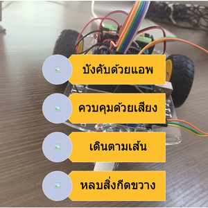
โปรเจค หุ่นยนต์ Arduino 4in1 - บังคับด้วยแอพ / ควบคุมด้วยเสียงปรบมือ / เดินตามเส้น / หลบสิ่งกีดขวาง
1 ปีที่ผ่านมา
ชุดคิท หุ่นยนต์ Arduino 4in1 - บังคับด้วยแอพ / ควบคุมด้วยเสียงปรบมือ / เดินตามเส้น / หลบสิ่งกีดขวาง แบบ DIY (มี ขั้นตอนวิธีทำ และ โค้ด)ชุดคิท หุ่นยนต์ Arduino 4in1 ชุดนี้ สามารถ ทดสอบ ทำโปรเจค ได้หลากหลายรูปแบบ เหมาะสำหรับ โรงเรียน สถานศึกษา ใช้ในการ…
1 ปีที่ผ่านมา
ชุดคิท หุ่นยนต์ Arduino 4in1 - บังคับด้วยแอพ / ควบคุมด้วยเสียงปรบมือ / เดินตามเส้น / หลบสิ่งกีดขวาง แบบ DIY (มี ขั้นตอนวิธีทำ และ โค้ด)ชุดคิท หุ่นยนต์ Arduino 4in1 ชุดนี้ สามารถ ทดสอบ ทำโปรเจค ได้หลากหลายรูปแบบ เหมาะสำหรับ โรงเรียน สถานศึกษา ใช้ในการ…
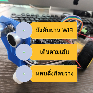
โปรเจค หุ่นยนต์ ESP8266 3in1 - บังคับผ่าน WIFI / เดินตามเส้น / หลบสิ่งกีดขวาง
1 ปีที่ผ่านมา
ชุดคิท หุ่นยนต์ ESP8266 3in1 - บังคับผ่าน WIFI / เดินตามเส้น / หลบสิ่งกีดขวาง แบบ DIY (มี ขั้นตอนวิธีทำ และ โค้ด)ชุดคิท หุ่นยนต์ ESP8266 V3 3in1 ชุดนี้ สามารถ ทดสอบ ทำโปรเจค ได้หลากหลายรูปแบบ เหมาะสำหรับ โรงเรียน สถานศึกษา ใช้ในการเรียนรู้การสร้างหุ่…
1 ปีที่ผ่านมา
ชุดคิท หุ่นยนต์ ESP8266 3in1 - บังคับผ่าน WIFI / เดินตามเส้น / หลบสิ่งกีดขวาง แบบ DIY (มี ขั้นตอนวิธีทำ และ โค้ด)ชุดคิท หุ่นยนต์ ESP8266 V3 3in1 ชุดนี้ สามารถ ทดสอบ ทำโปรเจค ได้หลากหลายรูปแบบ เหมาะสำหรับ โรงเรียน สถานศึกษา ใช้ในการเรียนรู้การสร้างหุ่…
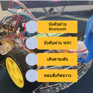
โปรเจค หุ่นยนต์ ESP32 5 in 1 - บังคับผ่าน Bluetooth / บังคับผ่าน WIFI / บังคับผ่านอินเตอร์เน็ต / เดินตามเส้น / หลบสิ่งกีดขวาง
1 ปีที่ผ่านมา
ชุดคิท หุ่นยนต์ ESP32 5 in 1 - บังคับผ่าน Bluetooth / บังคับผ่าน WIFI / บังคับ ผ่านอินเตอร์เน็ต/ เดินตามเส้น / หลบสิ่งกีดขวาง แบบ DIY (มี ขั้นตอนวิธีทำ และ โค้ด)ชุดคิท หุ่นยนต์ ESP32 4in1 ชุดนี้ สามารถ ทดสอบ ทำโปรเจค ได้หลากหลายรูปแบบ เหมาะสำหรับ โรง…
1 ปีที่ผ่านมา
ชุดคิท หุ่นยนต์ ESP32 5 in 1 - บังคับผ่าน Bluetooth / บังคับผ่าน WIFI / บังคับ ผ่านอินเตอร์เน็ต/ เดินตามเส้น / หลบสิ่งกีดขวาง แบบ DIY (มี ขั้นตอนวิธีทำ และ โค้ด)ชุดคิท หุ่นยนต์ ESP32 4in1 ชุดนี้ สามารถ ทดสอบ ทำโปรเจค ได้หลากหลายรูปแบบ เหมาะสำหรับ โรง…
โปรเจค ESP32 เปิด-ปิดไฟ ผ่านอินเตอร์เน็ตด้วย ESP Rainmaker
2 ปีที่ผ่านมา
ESP RainMaker เป็นแพลตฟอร์มที่ช่วยให้นักพัฒนาสร้างอุปกรณ์ที่เชื่อมต่อกับ ESP32-S2 SoC ของ Espressif โดยไม่ต้องวุ่นวายกับการจัดการโครงสร้างพื้นฐาน มี SDK ของอุปกรณ์ แอปโทรศัพท์ที่ปรับเปลี่ยนได้เอง มิดเดิลแวร์คลาวด์แบบโปร่งใส และยูทิลิตีโฮสต์เพื่อลดควา…
2 ปีที่ผ่านมา
ESP RainMaker เป็นแพลตฟอร์มที่ช่วยให้นักพัฒนาสร้างอุปกรณ์ที่เชื่อมต่อกับ ESP32-S2 SoC ของ Espressif โดยไม่ต้องวุ่นวายกับการจัดการโครงสร้างพื้นฐาน มี SDK ของอุปกรณ์ แอปโทรศัพท์ที่ปรับเปลี่ยนได้เอง มิดเดิลแวร์คลาวด์แบบโปร่งใส และยูทิลิตีโฮสต์เพื่อลดควา…

โปรเจค Arduino เปิด-ปิดไฟ ด้วย โทรศัพท์ ผ่าน แอพบลูทูธ
2 ปีที่ผ่านมา
โปรเจค Arduino: เปิด-ปิดไฟด้วย โทรศัพท์ ผ่าน แอพบลูทูธ การควบคุมการเปิด-ปิดไฟในบ้านหรือสถานที่ต่าง ๆ ได้ง่ายขึ้นด้วยการใช้ Arduino ร่วมกับบลูทูธ. ในบทความนี้, เราจะสร้างโปรเจคที่ใช้ Arduino เพื่อควบคุมไฟผ่านแอพบลูทูธบนโทรศัพท์มือถือของเรา. การทำโปรเจ…
2 ปีที่ผ่านมา
โปรเจค Arduino: เปิด-ปิดไฟด้วย โทรศัพท์ ผ่าน แอพบลูทูธ การควบคุมการเปิด-ปิดไฟในบ้านหรือสถานที่ต่าง ๆ ได้ง่ายขึ้นด้วยการใช้ Arduino ร่วมกับบลูทูธ. ในบทความนี้, เราจะสร้างโปรเจคที่ใช้ Arduino เพื่อควบคุมไฟผ่านแอพบลูทูธบนโทรศัพท์มือถือของเรา. การทำโปรเจ…
โปรเจค Arduino ไฟฟ้าจากผลไม้ กับ หลอดไฟ 220 โวลต์
2 ปีที่ผ่านมา
สอนทำโปรเจค Arduino ไฟฟ้าจากผลไม้ กับ หลอดไฟ 220 โวลต์ "ทดลองไฟฟ้าจากผลไม้" เป็นการทดลองทางวิทยาศาสตร์ที่น่าสนใจเพื่อศึกษาและทดสอบกระบวนการผลิตไฟฟ้าโดยใช้มันฝรั่งในฐานะวัตถุดิบหลัก. การทดลองนี้มุ่งเน้นการเรียนรู้และทำความเข้าใจถึงพลังงานที่เกิดขึ้นจา…
2 ปีที่ผ่านมา
สอนทำโปรเจค Arduino ไฟฟ้าจากผลไม้ กับ หลอดไฟ 220 โวลต์ "ทดลองไฟฟ้าจากผลไม้" เป็นการทดลองทางวิทยาศาสตร์ที่น่าสนใจเพื่อศึกษาและทดสอบกระบวนการผลิตไฟฟ้าโดยใช้มันฝรั่งในฐานะวัตถุดิบหลัก. การทดลองนี้มุ่งเน้นการเรียนรู้และทำความเข้าใจถึงพลังงานที่เกิดขึ้นจา…
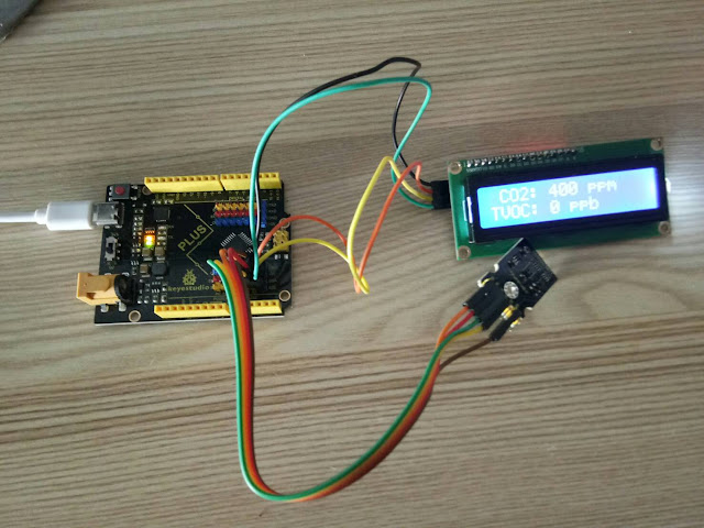
มินิโปรเจค Arduino วัดก๊าซคาร์บอนไดออกไซด์ แสดงผลที่จอ LCD
4 ปีที่ผ่านมา
ระดับคาร์บอนไดออกไซด์ปกติ (Normal CO2 Levels) ระดับคาร์บอนไดออกไซด์ปกติผลกระทบของ CO2 ต่อผู้ใหญ่ที่มีสุขภาพที่ดีสามารถสรุปได้ดังนี้-ระดับกลางแจ้งปกติ: 350 – 450 ppm-ระดับที่ยอมรับได้: <600 ppm=”” span=””>-ข้อร้องเร…
4 ปีที่ผ่านมา
ระดับคาร์บอนไดออกไซด์ปกติ (Normal CO2 Levels) ระดับคาร์บอนไดออกไซด์ปกติผลกระทบของ CO2 ต่อผู้ใหญ่ที่มีสุขภาพที่ดีสามารถสรุปได้ดังนี้-ระดับกลางแจ้งปกติ: 350 – 450 ppm-ระดับที่ยอมรับได้: <600 ppm=”” span=””>-ข้อร้องเร…
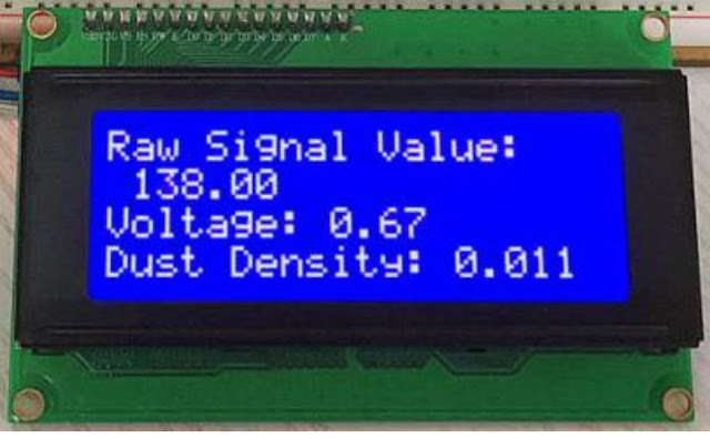
มินิโปรเจค Arduino เครื่องวัดฝุ่น PM2.5 ด้วย เซ็นเซอร์ GP2Y1014AU
4 ปีที่ผ่านมา
เครื่องวัดฝุ่น PM2.5 ด้วย เซ็นเซอร์ GP2Y1014AU บทความนี้ กล่าวถึงขั้นตอนการทำงานโปรเจค เครื่องวัดฝุ่น PM2.5 กับ Arduino UNO โดยใช้ เซ็นเซอร์วัดฝุ่น PM2.5 Keyestudio GP2Y1014AU ของ Sharp เซ็นเซอร์ฝุ่นนี้มีขนาดเล็กและสามารถตรวจจับฝุ่นละอองและอนุภาคควัน…
4 ปีที่ผ่านมา
เครื่องวัดฝุ่น PM2.5 ด้วย เซ็นเซอร์ GP2Y1014AU บทความนี้ กล่าวถึงขั้นตอนการทำงานโปรเจค เครื่องวัดฝุ่น PM2.5 กับ Arduino UNO โดยใช้ เซ็นเซอร์วัดฝุ่น PM2.5 Keyestudio GP2Y1014AU ของ Sharp เซ็นเซอร์ฝุ่นนี้มีขนาดเล็กและสามารถตรวจจับฝุ่นละอองและอนุภาคควัน…
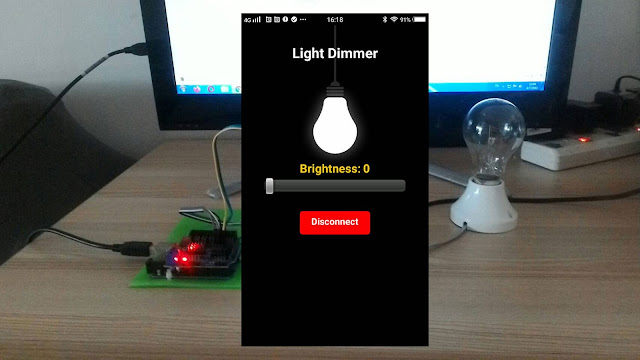
มินิโปรเจค Arduino หรี่ไฟ AC 220V ผ่านบลูทูธ ด้วย App Android
5 ปีที่ผ่านมา
หรี่ไฟ AC 220V ผ่านบลูทูธ ด้วย App Android เป้าหมายและหลักการทำงานของโปรเจค ต้องการหรี่ไฟ หรือควบคุมแสงสว่างของหลอดไฟหรืออุปกรณ์ไฟฟ้าอื่นๆ แบบไร้สายผ่านโทรศัพท์มือถือด้วยแอพแอนดรอยด์ (App Android) เพื่อเป็นการประหยัดพลังงาน และความสะดวกในการควบคุม ซึ…
5 ปีที่ผ่านมา
หรี่ไฟ AC 220V ผ่านบลูทูธ ด้วย App Android เป้าหมายและหลักการทำงานของโปรเจค ต้องการหรี่ไฟ หรือควบคุมแสงสว่างของหลอดไฟหรืออุปกรณ์ไฟฟ้าอื่นๆ แบบไร้สายผ่านโทรศัพท์มือถือด้วยแอพแอนดรอยด์ (App Android) เพื่อเป็นการประหยัดพลังงาน และความสะดวกในการควบคุม ซึ…

มินิโปรเจค สร้างเกม Endless Runner ด้วย Arduino และ จอ LCD
5 ปีที่ผ่านมา
มินิโปรเจค สร้างเกม Endless Runner ด้วย Arduino และ จอ LCD การสร้างเกม ก็คือการเขียนโปรแกรมแบบหนึ่ง ให้แสดงผลถี่ๆ แล้วเขียนโปรแกรมให้การแสดงผลในแต่ละครั้ง ค่อยๆทำให้ตัวละครในภาพค่อยๆขยับ โดยการทำการเปลี่ยนภาพ หรือเคลื่อนที่ตัวละคร ก็จะเกิดการเคลื่อนไ…
5 ปีที่ผ่านมา
มินิโปรเจค สร้างเกม Endless Runner ด้วย Arduino และ จอ LCD การสร้างเกม ก็คือการเขียนโปรแกรมแบบหนึ่ง ให้แสดงผลถี่ๆ แล้วเขียนโปรแกรมให้การแสดงผลในแต่ละครั้ง ค่อยๆทำให้ตัวละครในภาพค่อยๆขยับ โดยการทำการเปลี่ยนภาพ หรือเคลื่อนที่ตัวละคร ก็จะเกิดการเคลื่อนไ…
โปรเจค IoT ESP8266 วัดอุณหภูมิ บันทึกลงดาต้าเบส MySQL
5 ปีที่ผ่านมา
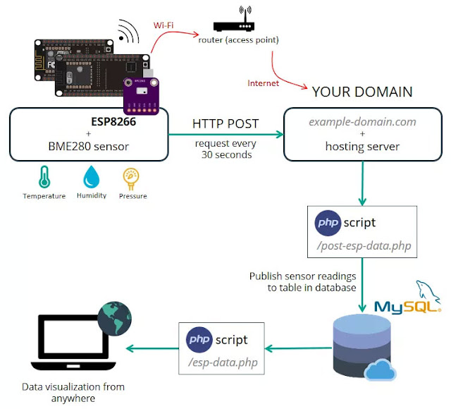
เป้าหมายของโปรเจคนี้คือเราต้องดูข้อมูลด้วยการเข้าถึงโดเมน ของเราเอง ไม่ว่าจะอยู่ส่วนไหนของโลก โดย ESP8266 จะสร้างไคลเอ็นต์ ที่ทำให้คำขอ HTTP POST ไปยังสคริปต์ PHP เพื่อแทรกข้อมูล (การอ่านเซ็นเซอร์) ลงในฐานข้อมูล MySQLโดยบทความนี้จะแสดงการส่งข้อมูลจาก…
5 ปีที่ผ่านมา
เป้าหมายของโปรเจคนี้คือเราต้องดูข้อมูลด้วยการเข้าถึงโดเมน ของเราเอง ไม่ว่าจะอยู่ส่วนไหนของโลก โดย ESP8266 จะสร้างไคลเอ็นต์ ที่ทำให้คำขอ HTTP POST ไปยังสคริปต์ PHP เพื่อแทรกข้อมูล (การอ่านเซ็นเซอร์) ลงในฐานข้อมูล MySQLโดยบทความนี้จะแสดงการส่งข้อมูลจาก…
มินิโปรเจค Arduino เปิดปิดไฟ 220V และ หรี่ไฟบ้านด้วยเสียง
5 ปีที่ผ่านมา
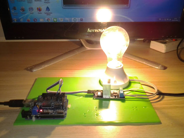
ควบคุมการติด-ดับ และ หรี่แสงสว่างหลอดไฟด้วยเสียงปรบมือ แนะนำ : ชุดประกอบสำเร็จ Arduino ควบคุมการติด-ดับ และ หรี่แสงสว่างหลอดไฟด้วยเสียงปรบมือ การทำ มินิโปรเจค Arduino เปิดปิดไฟ 220V และ หรี่ไฟบ้านด้วยเสียง เป้าหมายและหลักการทำงานของโปรเจค ต้องการควบค…
5 ปีที่ผ่านมา
ควบคุมการติด-ดับ และ หรี่แสงสว่างหลอดไฟด้วยเสียงปรบมือ แนะนำ : ชุดประกอบสำเร็จ Arduino ควบคุมการติด-ดับ และ หรี่แสงสว่างหลอดไฟด้วยเสียงปรบมือ การทำ มินิโปรเจค Arduino เปิดปิดไฟ 220V และ หรี่ไฟบ้านด้วยเสียง เป้าหมายและหลักการทำงานของโปรเจค ต้องการควบค…

โปรเจค ESP32-CAM กล้องดักถ่ายภาพอัตโนมัติ ด้วย PIR Motion
5 ปีที่ผ่านมา
โปรเจค ESP32-CAM กล้องดักถ่ายภาพอัตโนมัติ ด้วย PIR Motion โดยโปรเจคนี้ สามารถประยุกต์เป็นกล้องดักถ่ายภาพเมื่อมีผู้บุกรุก หรือเป็นกล้องดักถ่ายภาพสัตว์ มีชื่อเรียกหลายชื่อได้แก่ Trail Cam, Scout Cam, Camera Trap โดยผู้ใช้งานโดยซ่อนไว้ใกล้บริเวณทางที่สั…
5 ปีที่ผ่านมา
โปรเจค ESP32-CAM กล้องดักถ่ายภาพอัตโนมัติ ด้วย PIR Motion โดยโปรเจคนี้ สามารถประยุกต์เป็นกล้องดักถ่ายภาพเมื่อมีผู้บุกรุก หรือเป็นกล้องดักถ่ายภาพสัตว์ มีชื่อเรียกหลายชื่อได้แก่ Trail Cam, Scout Cam, Camera Trap โดยผู้ใช้งานโดยซ่อนไว้ใกล้บริเวณทางที่สั…
มินิโปรเจค Arduino อ่านค่าสี เล่นไฟล์เสียงจาก SD Card ออกลำโพง
6 ปีที่ผ่านมา
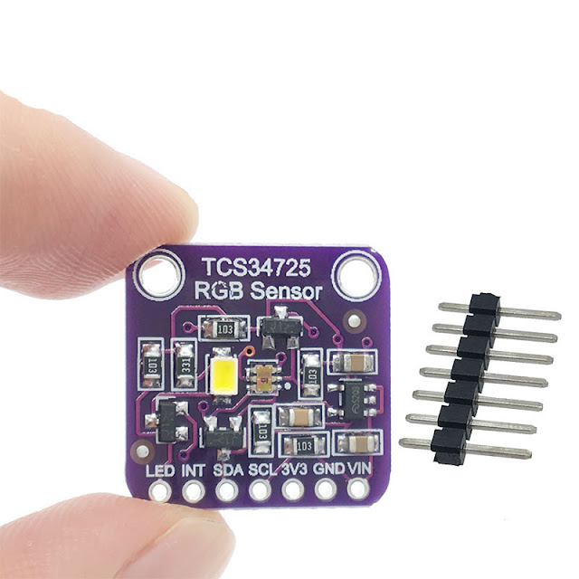
มินิโปรเจค Arduino อ่านค่าสี เล่นไฟล์เสียงจาก SD Card ออกลำโพง โปรเจค Arduino พูดโต้ตอบได้ โดยการเล่นไฟล์เสียงจาก SD Card บทความนี้จะสอนใช้งาน Arduino เล่นไฟล์เสียงจาก SD Card ออกลำโพง เราสามารถอัดเสียงพูดหรือบันทึกเสียงเพลงลง SD Card แล้ว สั่งงานให้…
6 ปีที่ผ่านมา
มินิโปรเจค Arduino อ่านค่าสี เล่นไฟล์เสียงจาก SD Card ออกลำโพง โปรเจค Arduino พูดโต้ตอบได้ โดยการเล่นไฟล์เสียงจาก SD Card บทความนี้จะสอนใช้งาน Arduino เล่นไฟล์เสียงจาก SD Card ออกลำโพง เราสามารถอัดเสียงพูดหรือบันทึกเสียงเพลงลง SD Card แล้ว สั่งงานให้…
 โรบอทสยาม อุปกรณ์หุ่นยนต์ Arduino
สมัครสมาชิกร้านนี้ เพื่อรับสิทธิพิเศษ


▲
▼
รายการสั่งซื้อของฉัน
รายการสั่งซื้อของฉัน
ข้อมูลร้านค้านี้

โรบอทสยาม อุปกรณ์หุ่นยนต์ Arduino
จําหน่าย อุปกรณ์หุ่นยนต์ Arduino , ESP8266, ESP32 , STM32 , micro:bit , Paspberry Pi รับประกอบหุ่นยนต์ ชุดคิทหุ่นยนต์ ตัวอย่างโปรเจค IoT (Internet of Things) อินเทอร์เน็ตของสรรพสิ่ง
เบอร์โทร : 095-226-2116
อีเมล : robotsiam16@gmail.com
อีเมล : robotsiam16@gmail.com
ส่งข้อความติดต่อร้าน
เกี่ยวกับร้านค้านี้
ค้นหาสินค้าในร้านนี้
ค้นหาสินค้า
สินค้าที่ดูล่าสุด
บันทึกเป็นร้านโปรด
Join เป็นสมาชิกร้าน
แชร์หน้านี้
แชร์หน้านี้
↑
TOP เลื่อนขึ้นบนสุด
TOP เลื่อนขึ้นบนสุด
สินค้าในตะกร้า ({{total_num}} รายการ)

ขออภัย ขณะนี้ยังไม่มีสินค้าในตะกร้า
ราคาสินค้าทั้งหมด
฿ {{price_format(total_price)}}
- ฿ {{price_format(discount.price)}}
ราคาสินค้าทั้งหมด
{{total_quantity}} ชิ้น
฿ {{price_format(after_product_price)}}
ราคาไม่รวมค่าจัดส่ง
➜ เลือกซื้อสินค้าเพิ่ม